Gen. IV oil catch can installation

venomred

Enthusiast
Joined
Mar 23, 2009
Posts
41
Reaction score
0
Location
Charleston, SC
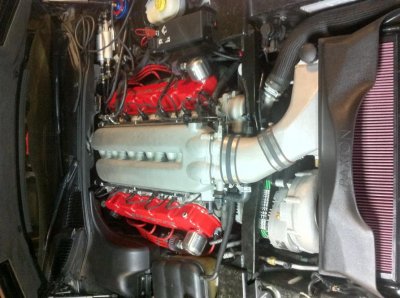
I'd like to install an oil catch can on my '08 coupe and have seen "how to" articles for earlier models but not the '08 and up.
Does anyone have instructions (Pics?) of installing one between the
PVC valve and the intake and what fittings are needed...THANKS!!
 

redtanrt10

Enthusiast
Joined
Oct 21, 2006
Posts
1,711
Reaction score
49
Location
Dana Point CA
Venomred, we just finished putting one on my '08 a couple of weeks ago. I took a number of pictures with the intention of posting as a DIY. To answser your question, we put plugs on the both the intake as well as the airbox, and run the lines from the PCV (hollowed out) and other valve cover to the can. The can is from Jeg's and has a K&N type breather. Other's have vented the intake to the can. mine won't pass CA emissions on a visual. I'll try and post in a day or two. In the mean time check w/DC Performance, they are or have created one for sale. I think Dan said they wanted $350.00? I'm sure it's a quality, well engineered set-up. You can probably build one for $125.00 on the low end, I think I have about $225.00 of parts on mine. Mike
 
OP
OP
V

venomred

Enthusiast
Joined
Mar 23, 2009
Posts
41
Reaction score
0
Location
Charleston, SC
Thanks for the good and prompt answers! However, I want to keep the vacuum through the PVC valve to the intake manifold and therefore to place the can between the PVC and the intake manifold keeping the fresh
air tube to the drivers side valve cover intact. My question is that
the fitting from the PVC appears to be about 1" (without measuring) and
the inlet to the catch can is about 1/2". Any ideas of fittings, tubing and placement of the can in the engine compartment will be appreciated!! Thanks!
 

Proshop

Viper Owner
Joined
Jan 9, 2010
Posts
131
Reaction score
0
These are waaaaay better.
 

Attachments

  • photo.jpg
    photo.jpg
    96.3 KB · Views: 258

treesnake

Enthusiast
Joined
Jan 19, 2006
Posts
2,288
Reaction score
2
Location
St.L
This is an ACRX. You can see the placemant of the catch can to the left of the air intake.

 
Joined
Jun 8, 2005
Posts
4,969
Reaction score
0
Location
Omaha NE.
The valve covers of the ACRX are redone by Arrow Racing Engines to address the pooling of oil in the head. They pull from a changed position and this setup will be offered on an exchange basis by Arrow at some point soon.
 

Viper X

Former VCA National President
VCA Officer
Joined
May 1, 2004
Posts
3,471
Reaction score
2
The valve covers of the ACRX are redone by Arrow Racing Engines to address the pooling of oil in the head. They pull from a changed position and this setup will be offered on an exchange basis by Arrow at some point soon.

Yes, they pull from a very low position on the outside of the valve covers, which seems less than ideal. Hope they changed something inside the valve covers to prevent oil from getting into the two hoses.

Dan
 

THEMASH

Enthusiast
Joined
Apr 15, 2001
Posts
705
Reaction score
0
Location
VA/KSA
Which catch can works better, the DC performance setup, or the ACRX/Arrow set up ?
Thanks
 
Last edited:

F8L SNK

Enthusiast
Joined
Oct 25, 2006
Posts
581
Reaction score
0
Location
Spring, TX.
The ACR X system does not draw from a low position on the valve cover. It is as high on the side of the valve cover as possible. It is in the center of the valve cover as well. It draws from above the metal plate inside the valve cover that keeps oil from being drawn into the breather system as much as possible. The ACR X "can" will NOT bolt into a normal Viper. The X location does not have the A/C line in the way for obvious reasons (no A/C on the X) On the normal Vipers this will have a large a/c line in the way and will not allow mounting.
 

F8L SNK

Enthusiast
Joined
Oct 25, 2006
Posts
581
Reaction score
0
Location
Spring, TX.
Detailed pics of ACR X system
You must be registered for see images attach


You must be registered for see images attach


You must be registered for see images attach


You must be registered for see images attach


You must be registered for see images attach


You must be registered for see images attach


You must be registered for see images attach


You must be registered for see images attach


You must be registered for see images attach


You must be registered for see images attach
 

Viper Specialty

Legacy/Supporting Vendor
Supporting Vendor
Joined
Feb 14, 2002
Posts
5,710
Reaction score
53
Location
Cape Coral, FL
I will definitely be working on something in short order... I am not blown back by anything I have seen, and anyone who knows me- knows that means back to the drawing board, I will fix it and make it RIGHT. :2tu:
 

F8L SNK

Enthusiast
Joined
Oct 25, 2006
Posts
581
Reaction score
0
Location
Spring, TX.
For those who may or may not know what a catch can is for:

The crank case MUST be vented to keep from developing too much crank case pressure. The factory must vent the crankcase to recirculate back into the engine. This is done for emission purposes. The oil puddling in the intake shows the negative to this design. A catch can is to allow the crank case to be vented and collect the oil that is ALWAYS forced out of the vent. The location of the venting will reduce the amount of oil expelled through the vent.

You can still run a sealed system with a catch can by basically removing the air filter you see in these pictures and running a line to a vacuum source on the engine. The factory uses the air box that will have a small amount of vacuum to draw the vented air back into the motor. The catch can is then basically an air/oil separator and will keep the oil in the can and allow clean air from the crank case to be pulled back into the engine. This system will be emission compliant (yet not necessarily CARB approved).

The catch can in either scenario WILL have to be drained on a periodic basis to keep it from filling up. In a normally aspirated configuration the amount of crank case pressure is not very high, obviously in a boosted application it will be higher. This will require larger vent holes, lines and capacity to move air than a naturally aspirated combination.

This is not meant to say what design is right or wrong but allow people to understand what this is even for.

The reason you do not want oil in the engine is basic. Oil is flammable and can cause detonation. Detonation is the combustion cycle taking place to early and causing pre detonation (knock).

Hope this helps some understand why this is even important to consider
 
Last edited:

BAD BOYZZ GARAGE

Enthusiast
Joined
Feb 23, 2010
Posts
720
Reaction score
0
Location
Sacramento
The Arrow conversion looks good. The valve covers are a pretty tight fit over the valve train ( rocker system ), so I am sure they took all those factors into consideration when making the placement choice. If there is anything to improve on I am sure Arrow has that under control.

Good pictures also of the =BAD BOYZZ SERIES= ACRX headers:usa:

Ciao,
BAD BOYZZ GARAGE, INC.
Toddy Gomez - President
 

hightest

Enthusiast
Joined
Oct 5, 2008
Posts
69
Reaction score
0
Coudn't you just install a catch can between the existing PCV valve and intake manifold port, as well as a second catch can between the drivers side valve cover port and air filter intake port? This would make the PCV system still CARB compliant for everyone and still stop the oil buildup in the intake tract.
AMW (accurate machine works) makes a good small billet catch can with a drain valve and baffling that is relatively well priced.
I used this catch can with the same crankcase routing for my supercharged corvette and it worked very well.
just my .02
 

Cop Magnet

Enthusiast
Joined
Jun 11, 2003
Posts
2,533
Reaction score
0
Location
Kenilworth, IL
That Jegs piece looks REALLY small. Those are 1/4" fittings, which makes the capacity look like about an ounce of oil.
 

Viper X

Former VCA National President
VCA Officer
Joined
May 1, 2004
Posts
3,471
Reaction score
2
The catch can I developed and installed is working very, very well. Very little oil in it (with 2 -10 AN lines and a large capacity billet can) in 8 track events pulling 1.5 + G's in an 09 ACR. It is also easily converted back to OE for emissions testing.

PM if interested, provide your direct email and I'll send a parts list and pics.

.....and no, I don't sell them, you'll have to buy your own parts and put the system together like I did which is very simple. Parts cost is about $200.

Dan
 

ROCKET62

Has Left the Room!
Joined
Mar 6, 2003
Posts
2,392
Reaction score
0
Location
Phoenix, AZ bye-bye IOWA
I was thinking that it looks like a shot glass - so roughly 2 oz. Sure hope a new Gen 4 isn't blowing that much oil thru the pvc system. As Viper X stated - very little oil after 8 track events in his '09. Probably not the solution you're looking for if you're running a blower - but for a stock application - looks like a simple solution that would install easy and use the same PVC tubing.

That Jegs piece looks REALLY small. Those are 1/4" fittings, which makes the capacity look like about an ounce of oil.
 

Latest posts

Members online

Forum statistics

Threads
153,191
Posts
1,681,858
Members
17,686
Latest member
Javadog62
Top