Steve M

Enthusiast
Joined
Dec 29, 2011
Posts
1,071
Reaction score
202
Location
Dayton, OH

Introduction​

The 2-3 people that follow me on Instagram (@sidepipedsnake) have figured out that I’ve been busy lately rebuilding the differential in my ’08 Viper. There is nothing new about what I’m doing – as a matter of fact, Viper owner Bryan Cowger (a.k.a. @cowger) did exactly what I set out to do about 10 years ago, and he was kind enough to document his adventure here:

https://www.viperclub.org/vca/threads/my-diy-differential-gear-change.659129/

Unfortunately, as is the case with many great write-ups on various forums around the internet, his pictures no longer work (many thanks, and a hearty f*** you to Photobucket). I reached out to Bryan through the forum, and he was kind enough to email me every single one of his pictures, which was hugely helpful. It is not my intent, however, to recreate his old thread. I can do that at a later date when/if I get the time and have his permission to do so, but now is not that time.

Even after going over and over his posts and scouring the internet for hours on end sifting through the information that’s out there (both good and bad), I still had so many questions to which I had no answers. I’ve spent the better part of the past 2 months working on this project off and on as time permitted, and I’ve learned so many things along the way. My intent is to share what I’ve learned with the broader Viper community in hopes that it will inspire other owners, much like Bryan inspired me, to tackle this job.
 
OP
OP
Steve M

Steve M

Enthusiast
Joined
Dec 29, 2011
Posts
1,071
Reaction score
202
Location
Dayton, OH

Background/Motivation​

First and foremost, this rebuild was not done out of necessity. I am fortunate to have two complete differentials in my possession – the one that originally came with my car with 3.07 gears and the stock GKN Visco Lok, and a fully assembled Gen 5 differential (w/ 3.55s and the same GKN Visco Lok) I ordered and installed about 5 years ago that I'll document in another thread.

Drag radials were not kind to my original differential – when I took it out back in 2017, it had some pretty serious gear whine, and was making noises that were not comforting. Once the Gen 5 differential arrived on my door step, I took the original one out and ended up storing it in my shed, knowing that one day it would need a rebuild.

The Gen 5 differential has held up to a substantial amount of abuse, and although it has picked up some gear whine over the past few years (mostly thanks to Hoosier drag radials and the Nth Moto clutch), it continues to work without issue. After this little experiment, it will also go into storage, and I may end up refreshing it at some point in the future now that I have the knowledge/tools/skills to do it myself.

Rebuilding a differential is one of those things that has always seemed a little beyond my ability to tackle, but I also don’t know of any shops around me that would take on the job, or if they would, do it to my satisfaction. Time is money, and shops need to make a profit, but as I have learned, rushing a differential rebuild is not something anyone should do. That’s why I’m a big fan of DIY – it’s mostly because I don’t trust people to do the job right.

Many years ago, I had a 2002 Camaro SS with an aftermarket 12-bolt axle, and that sumbitch whined like a banshee from the moment it rolled out of my garage with that 12-bolt installed. The gear whine completely ruined the driving experience, but I didn’t have the tools, time, or confidence to try to rebuild it myself, and I certainly didn’t know who I could trust to do the job to my satisfaction. I sold that car shortly after I bought my Viper, but I always regretted not getting that fixed, or at least trying to do it myself.

That ends now.

It’s going to take me a while to put together all of my thoughts and pictures into a somewhat coherent story, so please be patient, and I’ll keep adding to this write-up as I have time. The information that follows applies to any Gen 3/4/5 Viper (2003-2017) differential, and most of it should also apply to the Gen I/II cars, so hopefully someone will find this helpful, especially as parts supplies continue to dry up and members move on to other platforms (and take their knowledge with them).
 
OP
OP
Steve M

Steve M

Enthusiast
Joined
Dec 29, 2011
Posts
1,071
Reaction score
202
Location
Dayton, OH

Disclaimer​

Let’s get this out of the way: I’m not a mechanic. I have no formal training when it comes to working on cars. Full stop.

I have been turning wrenches for ~20 years, and I’ve done many projects on all of my vehicles, including this one. Most of them I’d say have even been successful. But I’m not an expert, and I’ll gladly defer to anyone that is. If you see something that doesn’t seem right, feel free to ask, or just point it out. But I’d also ask that you offer an explanation instead of just criticism – that’s the only way we’re all going to learn and grow stronger as a community.

I will say, though, that I did consult with someone that has rebuilt many differentials (mostly Toyota products), and still does. He was kind enough to offer his wisdom and advice, all of which I’ll pass along to you when and where appropriate. I can’t say enough kind words about the gentleman who helped me – it was truly a blessing.
 
OP
OP
Steve M

Steve M

Enthusiast
Joined
Dec 29, 2011
Posts
1,071
Reaction score
202
Location
Dayton, OH

Warning​

This is a hugely time and resource intensive project. I lost count of the number of hours I spent swapping shims, painting gear teeth, reading patterns, and taking it all apart only to do it over again. And over. And over. This is a repetitive process, no two ways about it.

I also spent a small fortune in tools and specialty equipment, most of which I will likely never use again (except for maybe another differential rebuild). I’ll list what I bought, why I bought it, and where I think your hard-earned dollars are best spent.

The good news: this is not a difficult task, but it is a game where thousandths of an inch (like 0.001-0.002”) matter. And I have examples (with pictures) to back that up.

Still interested? Let’s dive in.
 
OP
OP
Steve M

Steve M

Enthusiast
Joined
Dec 29, 2011
Posts
1,071
Reaction score
202
Location
Dayton, OH

Viper Differential Information​

The 2003-2017 (Gen 3, 4, & 5) Dodge Vipers use the same basic design for the rear differential. The design is based on a Dana Super 44 differential, also known as a Dana 44HD, and sometimes (but rarely) known as a Dana 226.

What it is NOT is a standard Dana 44.

What’s the difference? The Dana Super 44 uses a larger diameter ring gear – 8.9” for the Super 44 vs. 8.5” for the standard Dana 44. As an aside, 8.9” converted to millimeters is 226 mm, hence the Dana 226 designation. The Super 44 ring gear is held to the carrier with ten (10) 7/16”-20 (fine thread) bolts, and are Grade 9 (very high strength). The Super 44 also uses a larger pinion gear with more splines at the pinion gear to yoke interface – 29 splines (1.626” pinion shaft diameter) for the Super 44 vs. 26 splines (1.375” pinion shaft diameter) for the standard Dana 44. The Super 44 bearings are also larger to handle heavier loads.

Bottom line: the Viper differential is a beefed-up Dana 44, so don’t go ordering parts for a standard Dana 44 (which was used in many vehicles, including Jeeps) hoping they will work in a Viper.

There are some minor differences by model year across the generations, but for the most part, the differential housings can be swapped from one generation to another (within Gen 3, 4, & 5 Vipers) without issue as the external mounting points are the same. The major differences are with the internals, specifically the limited slip units and ring and pinion gear ratios. Here’s the quick and dirty version:

Gen 3 (2003-2006) = Hydra-Lok Limited Slip w/ 3.07 ring and pinion gear ratio
Gen 4 (2008-2010) = GKN Visco-Lok Limited Slip w/ 3.07 ring and pinion gear ratio
Gen 5 (2013-2017) = GKN Visco-Lok Limited Slip w/ 3.55 ring and pinion gear ratio

It should be noted that the Gen 5 ACRs came with a finned rear cover for better passive cooling, but all else appears to be the same. The ACR differential cover can be used on Gen 3, 4, and non-ACR Gen 5 Vipers.

There are differences among the generations with the stub axles (the small splined shafts that come out of either side of the differential and attach to the axles), and the axles themselves. I covered all of this in detail with pictures in this post: https://driveviperforums.com/forums/threads/27560-Drexler-rear?p=433200&viewfull=1#post433200

Backwards compatibility goes something like this:

Axles:
Gen 3 and Gen 4 axles are interchangeable
Gen 3 and Gen 4 axles can be used with either Gen 3 or Gen 4 stub axles
Gen 5 axles can only be used with Gen 5 stub axles

Stub Axles:
Gen 3 stub axles cannot be used with the Gen 4/5 GKN Visco Lok differential due to the location of the internal retention ring grooves
Gen 4 stub axles can be used in a Gen 5, but you would have to use Gen 3/4 style axles
Gen 5 stub axles can be used in a Gen 4, but you have to use the Gen 5 axles

Note: most aftermarket carriers are not compatible with the OEM stub axles, and will come with their own stubs (I’ll address this later on when I get to what parts I installed).

For those that don’t understand ring and pinion gear ratios, I’ll offer the following (very basic) explanation.

The purpose of a ring and pinion is two-fold:
  • Direct the power from the engine/transmission/driveshaft to the driven wheels by turning it 90°
  • Act as a torque multiplier to get the car moving and keep it moving
The torque multiplication part is where the gear ratio comes into play. The pinion gear (the smaller one with the long shaft) and the ring gear (sometimes referred to as a crown gear) have a set number of teeth. The number of teeth is what gives you the gear ratio (after doing a little math). For the Gen 3/4/5 Vipers, the most common ones are:

  • 43 teeth ring gear, 14 teeth pinion gear; 43 divided by 14 is 3.0714 (a.k.a. 3.07 gears)
  • 39 teeth ring gear, 11 teeth pinion gear; 39 divided by 11 is 3.5454 (a.k.a. 3.55 gears)
  • 41 teeth ring gear, 11 teeth pinion gear; 41 divided by 11 is 3.7272 (a.k.a. 3.73 gears)
  • 43 teeth ring gear, 11 teeth pinion gear; 43 divided by 11 is 3.9090 (a.k.a. 3.91 gears)
For 3.07 gears, the pinion gear will turn approximately 3.07 times for each 1 time the ring gear turns. The gear ratio is how much the torque gets multiplied after going through the differential. Hopefully it is easy to see that a 3.91 gear ratio will provide more torque multiplication to the tires than a 3.07 gear ratio, but there are always pros/cons. As an example, for a given speed, say 70 MPH, the engine will operate at lower RPMs with 3.07s than it does with 3.91s. The benefit is that the 3.07s will run a bit cooler. The downside is that it can really bog the engine down, but that’s why they make a transmission with many gears to overcome that minor annoyance.

I chose to stay with Dana Spicer gears since they were/are an OEM supplier. Here are the part numbers for the gear ratios listed above:

3.07: 43/14 (ring/pinion); Dana Spicer part number 80739-5 (set) – Mopar part number 5093384AA
3.55: 39/11 (ring/pinion); Dana Spicer part number 84073-5 (set) – Mopar part number 68203459AA
3.73: 41/11 (ring/pinion); Dana Spicer part number 84212-5 (set)
3.91: 43/11 (ring/pinion); Dana Spicer part number 84213-5 (set)

When ordering gears, especially other brands, you need to make sure the ring gear diameter is correct (8.9"), and the pinion spline count and diameter are correct (29 splines, 1.626" diameter). If the company doesn't provide that information, call and ask - otherwise, you might end up with standard Dana 44 gears that won't work.

Important note: ring and pinion gears come as a matched set. You cannot mix and match ring and pinion gears, even if they are the same gear ratio from the same manufacturer. All ring and pinion sets come etched with matching identification numbers to keep them from getting mixed up. If you don’t see unique numbers/symbols etched on both gears, or if they don’t match, don’t go any further until you figure out what’s going on.

Here are a couple of good online references I found that may be useful to others:

https://www.pirate4x4.com/d1/tech/billavista/PDFs/Dana_light_axle_service_manual.pdf

https://d3qx1uccksbb2n.cloudfront.net/docs/XGI.pdf (see page 94)
 
Last edited:
OP
OP
Steve M

Steve M

Enthusiast
Joined
Dec 29, 2011
Posts
1,071
Reaction score
202
Location
Dayton, OH

Viper Differential Rebuild Parts​

Below is a list of the parts I ordered/received for this rebuild. Most of these supplies came from Jon B, and some I sourced myself (I’ll note those when/where applicable). I’m sure I’ll forget something, so if it looks like something is missing, please ask.

First, a picture:

You must be registered for see images attach


The details:

- Dana Spicer 3.73s: the gear ratio choice was a personal one, with a focus on drag racing. These might be a bit much for the street, but to be frank, so are the current 3.55s that I’ve been running, at least when it comes to traction in first and second gear.
- OS Giken Differential/Carrier (optional): I originally wanted a Wavetrac, but there weren’t any available when I was ordering parts. Jon B had an OS Giken sitting on the shelf, so after some thought, I went ahead and had him send it my way. This is not a cheap unit, but I know it has a very good reputation, and should be plenty stout for drag racing. I’ll make another post about this later.
- OS Giken-Specific Stub Axles (optional): as already stated in the post above, most aftermarket differentials require different stub axles. This is part of the reason why differentials can be so expensive. The OS Giken came with its own stub axles, so your old ones will not be reused.
- Nitro Gear Solid Pinion Spacer (optional): the differential rebuild kit that Jon provided came with a standard crush sleeve (pictured above). I’ll make another post about why I chose to do a solid pinion bearing spacer instead.
- Pinion Bearing Shims: the rebuild kit came with 8 different pinion bearing shims, which go under the inner pinion bearing and set the pinion depth. It included the following sizes (all measurements in inches): 0.040, 0.042, 0.045, 0.046, 0.0485, 0.050, 0.0525, 0.054. This assortment was sufficient to get me started, but I ended up ordering some additional shims once I started zeroing in on the proper gear mesh (more about this later).
- Carrier Bearing Shims: the rebuild kit came with 5 different carrier bearing shims, which go on either side of the carrier bearings in the differential case and set the backlash (this will all be shown later). It included the following sizes (all measurements in inches): 0.126, 0.129, 0.1315, 0.1345, 0.1375. Again, this was sufficient to get me started, but I ended up ordering additional carrier shims once I started getting close on the setup (more about this later).
- Pinion Bearings: Jon B’s rebuild kit included new Koyo pinion bearings. I have nothing against Koyo bearings, but I prefer US-made Timken bearings when I can get them. I’ll make a separate post about bearings, sizes, and part numbers later.
- Carrier Bearings: the rebuild kit included new Timken (US-made) carrier bearings.
- New Pinion Seal: you’ll end up destroying the original pinion seal during disassembly, so a new one is required. It will not be installed until final assembly.
- New Stub Axle Seals: these don’t necessarily have to be replaced unless you have some leaks, but it is never a bad idea to go with new ones. These can really be installed at any time, but probably best left until final assembly to prevent damage during setup trial/error.
- New Ring Gear Bolts: ring gear bolts are not reusable, so don’t even try. You’ve come this far, so why cut corners now? The rebuild kit came with 10 new 7/16”-20 Grade 9 bolts.
- New Pinion Nut and Washer: again, these should never be reused. The pinion nut is a one-time use type of item – it is a prevailing torque design (some of the threads are slightly deformed to keep it from backing off). You’ll want to source a non-locking pinion nut for setup – more about this later.
- New U-Joint Strap Hardware: the bolts and straps the hold the driveshaft to the pinion yoke should never be reused. The rebuild kit came with new hardware, Spicer part number 3-70-48x.
- Permatex Ultra-Grey RTV: this was provided in the rebuild kit, and is what you'll use to seal the differential cover to the housing. This particular variant is specified for high vibration, high torque applications, which seems fitting for a differential.

And here is a list of parts that you can reuse:

- Oil Slinger
- Pinion Yoke
- Carrier Bearing Caps
- Carrier Bearing Cap Bolts
- Differential Cover Bolts
- Stub Axle Support Bearings (these are the needle roller bearings pressed into the sides of the case – more about these later)

You can also technically reuse any shims that come out of your existing differential, provided they are in good shape. Mine were, but I didn’t end up reusing any of them.

It should also be noted that no gear oil was provided. The type of gear oil you’ll end up using depends on the differential you choose, and you’ll need 3-4 quarts of it (to cover the initial fill + the oil change you’ll need to do after break-in). The OS Giken has very specific requirements, and the OEM fill does not meet those requirements. Again, more about this later.
 
OP
OP
Steve M

Steve M

Enthusiast
Joined
Dec 29, 2011
Posts
1,071
Reaction score
202
Location
Dayton, OH

Viper Differential Bearings​

There are 6 total bearings in the Viper’s differential that can be serviced – you’ll only be dealing with 4 of them.

The 2 you will (likely) not be dealing with are the stub axle support bearings that are pressed into the sides of the case where the stub axles enter (they sit just behind the stub axle seals). They are needle roller bearings, and look like this:

You must be registered for see images attach


These are not highly stressed, so as long as they look like they’re in good shape (mine were), you’ll just leave them where they are. Mine were Torrington brand bearings, part number B2412.

The 4 other bearings you will be replacing are the pair of carrier bearings that go on either side of the carrier, and the inner (larger) and outer (smaller) pinion bearings. The carrier and pinion bearings are tapered roller bearings, and come as a two-piece set. The inner piece is called the cone, and the outer piece is called the cup. The cone consists of multiple parts, including the inner race, the rollers (which ride on the tapered portion of the inner race), and the cage (which holds the rollers in place). The cup is a single piece, and provides the other tapered surface against which the rollers ride. A picture is probably worth more than what I just wrote:

You must be registered for see images attach


And another picture to give you an idea of the size differences among the inner and outer pinion bearings, and the carrier bearings:

You must be registered for see images attach


Two important notes on these:

1. Tapered roller bearings can be ordered as separate pieces (e.g. you can order only the cup, or only the cone). If you want the full bearing, you need to make sure you order a set that includes both halves.
2. You should not combine cups/cones from different manufacturers. This is specifically stated in the Dana Spicer light axle service manual referenced in one of my posts above (https://www.pirate4x4.com/d1/tech/billavista/PDFs/Dana_light_axle_service_manual.pdf), pg. 9.

To expand on the second point, take a look at the following picture that shows the cone assemblies from two different manufacturers (Timken and Koyo), both with the same part number:

You must be registered for see images attach


Both are replacements for the inner pinion bearing (the larger of the two on the pinion). The Timken bearing (left) uses fewer rollers than the Koyo bearing (right) – 17 rollers for Timken, 18 rollers for Koyo. The Timken inner race, against which the crush sleeve/solid spacer rides, is substantially beefier than what is used on the Koyo. I can’t quantify that one design is better than the other; they are just different. Even though they are not pictured, there are also subtle differences between the cups - the angles are slightly different between the two brands. In a game where thousandths of an inch matter, mixing and matching cups and cones from different manufacturers is not something you should consider doing, especially when new bearings are relatively cheap compared to the other parts of this build.

Tapered roller bearings require a certain amount of preload to ensure a long service life. Basically, the cup and cone assembly need pressure applied so that the rollers have good surface area contact with both the inner race and the cup (sometimes referred to as the outer race). Too little preload, and the rollers will develop hot spots from too little surface contact area. Too much preload will also generate too much heat. Too much heat will affect the heat treatment of the bearings – if that gets messed up, the bearings will destroy themselves.

The pinion bearing preload is set with either a crush sleeve or a solid pinion bearing spacer (more about that in the next post). The carrier bearing preload is set with the carrier shims that go between the carrier bearing cups and the differential case. I’ll talk about this again when I get into the final assembly stage.

Here are the part numbers for the carrier and pinion bearings:

Carrier Bearings (two sets required):​

Cup: LM603012
Cone: LM603049
Set: Timken Set 36 (includes one cup and one cone with the part numbers listed above)

Inner (Larger) Pinion Bearing (one set required):​

Cup: M802011
Cone: M802048
Set: Timken Set 328 (includes one cup and one cone with the part numbers listed above)

Outer (Smaller) Pinion Bearing (one set required):​

Cup: M88010
Cone: M88048
Set: Timken Set 63 (includes one cup and one cone with the part numbers listed above)

Prices are all over the place, so shop around if you are going to piece together a rebuild kit yourself.

Set-up Bearings​

Several companies offer “set-up bearings” – basically, these bearings have a modified inner race that can be slipped on and off without the need for a press. This allows you to easily change out shims that sit under a pressed-on bearing.

Pros: set-up bearings save you a lot of time when trying to zero in on the right shims. Every time you change the pinion depth, you have to change the shim under the bearing, and you’ll be doing this multiple times to get the gear mesh just right. If you have to press a bearing on and off each time you want to change the shim, you can see how this would add up.

Cons: as I found out, there may be slight differences with your setup once you press on the final bearings. I’ll show you why this ended up being an issue for me later, and why I think it happened.

Bottom line: if you are going to use a set-up bearing, do not pay the ridiculous prices I saw (like $100+ for a single bearing) – you can make one yourself.

For the Viper Dana Super 44, only one setup bearing is required: the inner (larger) pinion bearing (part number M802048, cone only). This is the only bearing that gets pressed on that has a shim underneath. The carrier bearing shims go on the outside of the bearing assembly, so set-up bearings for these would make no sense for this particular application. The outer (smaller) pinion bearing is an interference fit, and can be removed with a few taps of a hammer.

As a reminder, if you are going to make a set-up bearing for the inner pinion bearing, make sure it is the exact same brand as the one you'll be using for your final setup.

I’ve seen all sorts of methods for making your own set-up bearings, including using a die grinder or a flap wheel in a drill. I agonized over buying a die grinder or flap wheels for this purpose, but if you already have a Dremel, you don’t need any of that. All you need is an 80-grit sanding drum (a.k.a. sanding band), like this: https://www.dremel.com/us/en/p/445-26150445aa, and a little bit of patience. About a minute of taking one of those to the inner race removed enough material to allow the inner pinion bearing to slide on easily.
 
OP
OP
Steve M

Steve M

Enthusiast
Joined
Dec 29, 2011
Posts
1,071
Reaction score
202
Location
Dayton, OH

Crush Sleeve vs. Solid Spacer​


The pinion gear has two tapered roller bearings (outer and inner) that oppose each other, holding the pinion gear stationary in the differential housing (front-to-back and side-to-side) while still allowing it to rotate. As stated above, tapered roller bearings require a certain amount of preload to prolong their service life. That preload is established with a spacer located between the two pinion bearings, seated on the inner races of each bearing. This spacer is shown as #5 in the diagram below from the service manual:

You must be registered for see images attach


There are two design options for spacers – the standard crush sleeve, and a solid pinion spacer. The OEM Viper solution was a crush sleeve, and there’s a good reason for that when looking at it from a production standpoint.

Bearings and differential housings are all going to have varying tolerances from unit to unit in a mass production environment, so the amount of space between the inner races needed to establish the correct bearing preload, measured in inch-pounds of torque required to rotate the pinion gear, is also going to vary from one differential to the next. You could theoretically machine a spacer that is unique to each differential housing and set of bearings, but that would require thousands of different part numbers, and would be a nightmare from a serviceability standpoint since that same spacer would likely not work with a new set of bearings required for a rebuild.

That’s the beauty of a crush sleeve – it is made slightly longer than what is needed to establish the correct amount of preload, but is designed to crush under a load. That load is applied by tightening the pinion nut – during assembly, you keep tightening the pinion nut and measuring the pinion torque-to-rotate until you reach the desired preload. Now you have one part number, and you theoretically only need to assemble everything once, assuming you don’t overtighten the pinion nut (which would over crush the sleeve). That’s the downside of the crush sleeve – it is a one-time use item (for the most part), so if you mess up the assembly process by overtightening, you have to take it all back apart, install a new crush sleeve, and try again.

The other option is a solid pinion spacer. This sleeve is made from a substantially thicker tube of steel, and comes with a set of shims that you mix and match to achieve the correct amount of preload. But therein lies the downside – during the assembly process, it is yet another iterative step of putting it together, measuring the preload, and taking it back apart and trying another stack of shims if you don’t get it right on the first try (and you probably won’t). The solid sleeve is also more expensive, but that is theoretically offset by being reusable.

Again, a picture probably tells the story a little better when it comes to the differences between the two designs:

You must be registered for see images attach


It’s pretty clear how much beefier the solid sleeve is compared to the crush sleeve. And for reference, below is what the solid spacer shims look like:

You must be registered for see images attach


My solid spacer/sleeve came with 5 different shims of varying thicknesses: 0.010”, 0.012”, 0.013”, 0.016”, and 0.020”. They are super thin, and as I found out later, it is another part of the assembly process where single-digit thousandths of an inch matter.

To give you an idea of how much a crush sleeve needs to be compressed to achieve the correct amount of preload, consider the following picture:

You must be registered for see images attach


The difference between the two is only 0.042”, but that doesn’t mean much because I don’t know how long the original crush sleeve was. Regardless, it ain’t much.

So why would you pick one over the other?

That’s where the internet seems to be divided. Theoretically, the solid spacer should never deform under heavy loading due to its increased thickness, and thus would be the more reliable choice for heavy duty applications. There are many others out there that say the same for a crush sleeve – it should also never deform due to where it sits in the assembly.

I don’t have a good answer either way. I do know for a fact that the entire differential is subject to some pretty severe shock loading, especially if you encounter wheel hop. The aluminum case can certainly deform, but how much it does under shock loading is unknown. When do I encounter wheel hop? Pretty much every time I do a burnout at the drag strip. Is it enough to deform a crush sleeve and/or distort the housing? No clue.

But I guess I’ll find out. If this differential fails, I’ll just tear it apart and see what happened. I liked the idea of a beefier part for a pretty critical component of the assembly, but I wish I had some concrete numbers to back up my gut.

If you decide to go with a solid pinion spacer like I did, only one company makes them that I found: Nitro Gear & Axle. Link: https://www.nitro-gear.com/SKCSD44HD-p/skcsd44hd.htm

Many other companies distribute Nitro solid spacers, so if Nitro doesn’t have one in stock, you might be able to find one by asking around.

The solid spacer will run you about $60. For reference, a new crush sleeve is about $15, and as already mentioned above, the differential rebuild kit includes a new sleeve.

The choice is yours. I will likely never have enough data points to say which design is the better choice. Your intended use and budget will probably matter the most.
 
OP
OP
Steve M

Steve M

Enthusiast
Joined
Dec 29, 2011
Posts
1,071
Reaction score
202
Location
Dayton, OH

Shims​

I ended up having to deal with 3 different sizes/types of shims during this rebuild: solid pinion spacer shims (not required if using a crush sleeve), pinion shims, and carrier shims. It’s pretty easy to tell each one apart:

You must be registered for see images attach


To reiterate, the purpose of each shim is as follows:

1. Solid pinion spacer shims (only required if using a solid pinion spacer): these set the pinion bearing preload, which is done during final assembly.
2. Pinion shims: these set the pinion depth (i.e. where the pinion gear sits on the ring gear in reference to the ring gear/axle centerline). Thicker shims push the pinion deeper on the ring gear; this will also reduce backlash (but is not how backlash is set). Thinner shims pull the pinion gear out from the ring gear; this will increase backlash.
3. Carrier shims: these set the backlash (i.e. how much play there is between the ring and pinion gears) AND set the carrier bearing preload.

The solid pinion spacer shims sit between the spacer and the outer pinion bearing, and make contact with the outer pinion bearing inner race (part of the cone assembly). Picture for reference:

You must be registered for see images attach


The pinion shim sits under the inner pinion bearing cone, which is pressed on to the pinion gear:

You must be registered for see images attach


The carrier shims sit between the cup of the carrier bearings and the aluminum case:

You must be registered for see images attach


Tip: measure the shim thicknesses with a micrometer. Digital calipers also work, but my micrometer was more accurate/repeatable. Write the measurements on each with a black marker for easy reference.

As was already stated, the differential rebuild kit came with 8 pinion shims and 5 carrier shims, all of varying thickness. The Nitro solid pinion spacer came with 5 shims as well. The outer/inner diameter measurements for each type of shim are listed below:

1. Nitro Solid Pinion Spacer Shims: I.D. = 1.327”; O.D. = 1.6470”
2. Pinion Shims: I.D. = 1.646”; O.D. = 2.25”
3. Carrier Shims: I.D. = 2.25”; O.D. = 3”

You can order individual pinion shims from Chrysler/Dodge. They also offer sets of 5 shims over a set range thicknesses. Part numbers below (reference: https://roeracing.com/wp-content/uploads/2017/11/2008_Viper.pdf):

0.035” Pinion Shim: 68014932AA
0.036” Pinion Shim: 68014933AA
0.037” Pinion Shim: 68014934AA
0.038” Pinion Shim: 68014935AA
0.039” Pinion Shim: 68014936AA
0.040” Pinion Shim: 05017332AA
0.041” Pinion Shim: 05017333AA
0.042” Pinion Shim: 05017334AA
0.043” Pinion Shim: 05017335AA
0.044” Pinion Shim: 05017336AA
0.045” Pinion Shim: 05017337AA
0.046” Pinion Shim: 05017338AA
0.047” Pinion Shim: 05017339AA
0.048” Pinion Shim: 05017340AA
0.049” Pinion Shim: 05017341AA
0.050” Pinion Shim: 05017342AA
0.051” Pinion Shim: 05017343AA
0.052” Pinion Shim: 05017344AA
0.053” Pinion Shim: 05017345AA
0.054” Pinion Shim: 05017346AA

0.035” – 0.039” Pinion Shim Kit: 04856368
0.040” – 0.044” Pinion Shim Kit: 04856369
0.045” – 0.049” Pinion Shim Kit: 04856370
0.050” – 0.054” Pinion Shim Kit: 04856371

When I started zeroing in on my final pinion depth, I ordered the 0.040” – 0.044” pinion shim kit. As it turned out, I didn’t need it - the differential rebuild kit already had the correct thickness shim. That was very likely a lucky coincidence.

As for carrier shims, those are a bit easier to source outside of the Mopar parts supply chain. Yukon makes a carrier shim kit for the Dana 44HD that covers a wide range of shim thicknesses, part number SK 702005, available here: https://www.amazon.com/gp/product/B0078UBVVC/ref=ppx_yo_dt_b_search_asin_title?ie=UTF8&th=1

That kit included 12 different shims, a handful of which were in the range I needed for my rebuild.
 
OP
OP
Steve M

Steve M

Enthusiast
Joined
Dec 29, 2011
Posts
1,071
Reaction score
202
Location
Dayton, OH

Tools​

Below is a list of tools that are either optional, recommended, highly recommended, or required for this task (based on my personal experience). This won’t be absolutely everything, but it should include the bulk of things that some folks may not have in their tool box. These are in no particular order.

Tools I Bought (or already had)​

- Calipers: a good set of digital calipers come in very handy for many projects, especially this one.
Recommendation: https://www.mitutoyo.com/products/s...igimatic-calipers/absolute-digimatic-caliper/
Verdict: Highly Recommended. You can probably get by with cheaper calipers than the ones linked above.

- Micrometer: as mentioned above, I was able to get more precise, more consistent measurements of shims with a micrometer.
Recommendation: https://www.mitutoyo.com/products/s...gimatic-micrometers/coolant-proof-micrometer/
Verdict: Required. Again, you can probably get by with a cheaper micrometer.

- Hydraulic Press: you’ll need a floor standing hydraulic press to press on the carrier and inner pinion bearings. I was able to borrow a 20-ton press from a friend, but it was way overkill for this job. A 12-ton press would have been more than sufficient.
Recommendation: https://www.harborfreight.com/12-ton-shop-press-33497.html
Verdict: Required.
Alternative: the service manual states you can use a bearing hot plate like this: https://www.skf.com/us/products/mai...aters/heaters-for-mounting/electric-hot-plate. The heat will expand the inner race, allowing it to slide on. These can be quite pricey, so I would not entertain this purchase.

- Seal Drivers: the service manual lists seal drivers for both the pinion and stub axle seals. The pinion seal driver part number is Miller 8889, and the stub axle seal driver is Mopar part number C-4026B. Both can be seen in the pictures below:

You must be registered for see images attach


You must be registered for see images attach


Verdict: Recommended. I found a used pinion seal driver on Ebay for $20. The stub axle seal driver was a little harder to come by, and I ended up buying a new one. Both worked great, and provided seal support while also giving you something to bang on, which will keep you from damaging the seals. You’ll see these again later during final assembly.

- Dead Blow Hammer: rebuilding a differential is not a subtle operation. You’re going to be doing some banging, so a BFH will come in handy for many things throughout the process.
Recommendation: https://www.harborfreight.com/hand-.../4-lb-neon-orange-dead-blow-hammer-69004.html
Verdict: Required. I went with the 4-lb version, and I’m glad I did. That it is non-marring is a big bonus.

- Sledge Hammer: see above – there are some things that will need some persuading, like knocking out the old bearing races in the aluminum case.
Recommendation: https://www.harborfreight.com/3-lb-hardwood-engineers-hammer-69013.html?_br_psugg_q=sledgehammer
Verdict: Required. The 3-lb version was more than sufficient to get the job done.

- 1-5/16” Socket: this was an odd-ball size I didn’t have. It is what you’ll need to remove/reinstall the pinion nut.
Recommendation: https://www.amazon.com/Sunex-242D-2-Inch-16-Inch-Impact/dp/B000GHWO88
Verdict: Required. Sunex makes nice sockets, but there are many different manufacturers out there, so pick your poison.

- Clamshell Bearing Puller: this tool can be used to remove both pinion and carrier bearings without damaging either. If you end up getting this tool, you’ll need an impact (either electric or air powered) to use it. Video showing how it works here:


Recommendation: https://www.amazon.com/gp/product/B01N6SZ742/
Verdict: Highly Recommended. Prices for these things range from $100 all the way up to $500 for the name brand version. The cheap(er) one linked above worked great for me. If you get the tool linked above, you’ll also need a 36mm 6-point impact socket (https://www.amazon.com/TEKTON-6-Point-Impact-Socket-SID22136/dp/B08DK16GPN)
Alternative: you can also use a hydraulic press and a guillotine-style bearing separator, like this: https://www.harborfreight.com/bearing-separator-with-12-in-to-4-58-in-jaw-capacity-63662.html. If you go this route, you may have to modify the separator to fit under the pinion bearing properly.

- 1/2" Impact Wrench (Electric or Air): I can’t tell you how good modern electric impact wrenches are. If you don’t have one, I’d highly recommend getting one. My Milwaukee M18 Fuel 1/2" impact has earned its place in my tool box many times over. This thing will zip the old pinion nut off with a few ugga-duggas without breaking a sweat. I can’t say the same if you try to get it off by hand.
Recommendation: https://www.milwaukeetool.com/Products/Power-Tools/Fastening/Impact-Wrenches/2767-20
Verdict: Highly Recommended. Like really highly recommended.
Alternative: if you choose to remove the old pinion nut by hand, I’d highly recommend investing in a 3/4" breaker bar, like this one: https://www.amazon.com/TEKTON-4-Inch-40-Inch-Breaker-SBH00340/dp/B07H3KJQ83?th=1. My 1/2" breaker bar just wasn’t up to the task.

- Needle or Dial Style Inch-Pounds Torque Wrench: you’ll need one of these to measure the pinion torque to rotate when setting your pinion and carrier bearing preload. The needle style torque wrenches are way cheaper than the dial type, albeit at the expense of accuracy. I cheaped out on this part, but felt like the needle style worked well enough. You only need one that goes from 0-80 in-lbs.
Recommendation: https://www.amazon.com/gp/product/B01FMXEWQC/. These are typically 1/4" drive, so you’ll need an adapter to fit the 1/2" drive 1-5/16” socket listed above. This adapter worked great: https://www.amazon.com/gp/product/B07ZKPCZ65/
Verdict: Required.

- 3/8” Torque Wrench: any aspiring mechanic (shade-tree or otherwise) needs a good 20-100 ft-lbs, 3/8” drive torque wrench. You’ll use this to tighten the carrier bearing cap bolts, the ring gear bolts, and the differential cover bolts.
Recommendation: https://www.amazon.com/Precision-Instruments-PREC2FR100F-Wrench-Torque/dp/B000YOX568/. I love split-beam style torque wrenches – they are extremely easy to set, and don’t have to be dialed back to their lowest setting for storage.
Verdict: Required.

- 1/2” Torque Wrench: same as above, just bigger. This covers 50-250 ft-lbs. You’ll use this to tighten the pinion nut. It can also be used for the carrier bearing cap bolts and ring gear bolts, both of which are critical parts, so if you can only afford one, this is the size to get for this job.
Recommendation: https://www.amazon.com/Precision-Instruments-PREC3FR250F-Silver-Torque/dp/B002XMSFIM/?th=1.
Verdict: Required.

- Backlash Gauge: you’ll need this to measure backlash and ring gear runout; this will also be used to measure case distortion if you choose to use a case spreader (see below).
Recommendation: https://www.amazon.com/gp/product/B08W235VJW/. I’ll be frank, this thing was cheap Chinese garbage, but it did what I needed it to do. If I was going to do this for a living, I’d get a higher quality unit.
Verdict: Required.
Also Needed: the kit linked above includes a magnetic base to hold everything in place. That’s great and all, except for the fact that the Viper differential case is aluminum. The rod unscrews from the magnetic base, and has M8 x 1.25 metric threads. You can use a hex coupler stand-off nut (https://belmetric.com/steel-coarse-din-6334-3x-dia-hex-coupler-standoff-nut/?sku=NLONG8X24YLW) and a 31mm long M8 to M10 stepped stud (https://belmetric.com/m8-to-m10-stepped-stud-class-8-8-steel/?sku=S8X10X31YLW) to make an adapter – those two parts will allow you to screw the rod directly into the M10 x 1.5 tapped holes that accept the differential cover bolts. Problem solved.

- Case Spreader: this tool is completely optional. As the name indicates, it is used to spread the case apart to make getting the carrier in and out of the case easier. It looks something like this:

You must be registered for see images attach


The service manual lists the adapter plates as tool number 10033, and the spreader as tool number W-129-B. If you look up the spreader, you’ll see that it is $$$. Bryan (cowger) made his own.
Verdict: Optional. Why is it optional? Because it can be done with other methods that require substantially cheaper tools, and you won’t have to worry about spreading the case too far, which can damage it. Fast forward to 22:04 in this video to see how:


Bottom line: all you need is a 3/4" box end wrench + turning the pinion to get the carrier out, and your 4-lb dead blow hammer to get it back in. Screw getting a $600+ case spreader, or spending hours building one. If you do use a case spreader, the max you can spread it is 0.010” (source: service manual, page 5939).

- Pinion Yoke Holding Tool: you need something to hold the yoke in place while you wrench on the pinion nut.
Recommendation: https://www.amazon.com/gp/product/B07JGJ2LJ6/
Verdict: Required.
Also Needed: you’ll need bolts to attach this to the pinion yoke. You can use the ones that hold the u-joint straps in place, but they won’t give you much thread engagement in the yoke when using the tool linked above since it is 3/8” thick. The yoke threads are M8 x 1.0. I used these 30 mm under head length socket head bolts: https://www.fastenal.com/product/details/35753. They are grade 12.9, so they should hold up to some serious abuse while you are wailing on that pinion nut. Make sure you get some hardened washers to go under the bolts too: https://www.fastenal.com/product/details/11128387

- Bearing Race Driver Set: the pinion bearing cups (outer races) need to be pressed into the differential housing. A bearing race driver is needed to do that without damaging the races.
Recommendation: https://www.tooldiscounter.com/product/lisle-pinion-bearing-race-driver-set-lis59400
Verdict: Required. The Lisle 59400 set is very nice, and has the exact sizes need for this job. The outer (smaller) pinion bearing cup/race is 2-11/16” (2.6875”), and the inner (larger) pinion bearing cup/race is 3-1/4” (3.25”). If a race driver set doesn’t have these exact sizes (none of the Harbor Freight ones I looked at did), then they won’t work. Bonus: this set also includes a punch with extensions that came in very handy when knocking out the old races.

- Other Tools: 3/4" box end wrench, 3/4" 6-point socket (ring gear bolts), 19 mm 6-point socket (carrier bearing cap bolts), 13 mm 6-point socket (differential cover bolts), various ratchets (3/8” and 1/2" drive), a chisel with a blunt end, adjustable wrenches, metal files (for removing burrs), air compressor (to blow out holes and remove debris), etc. I know I’m forgetting stuff, but there really isn’t anything I can think of that is out of the ordinary for this type of job.

Tools I Made

I made a couple of custom tools that really came in handy for specific tasks. I ended up learning how to weld during this project, and I ended up using those skills to make 3 one-off tools – a breaker bar that worked with the pinion yoke holding tool referenced above, and 2 tools for pressing on the bearings. None of these are specifically required, but I used each many times.

- Breaker Bar: the pinion yoke holding tool has a place that accepts a breaker bar, but it does not come with one. I ordered a 3 foot long piece of mild steel square tubing, 1” x 1” x 0.120” wall thickness. The inside dimensions were good, but there was too much play with the outside, so I ended up building it up by welding on some extra material and grinding it down until it was a nice, tight fit (I added about 0.17” of extra material):

You must be registered for see images attach


- Bearing Press Adapters: when pressing on bearings, you need some way of only making contact with the inner race to avoid damaging the bearing during the process. As stated above, I made 2 press adapter tools – one for the carrier bearings, and one for the pinion bearings. I used the following supplies for each:

1. Carrier Bearing Press Adapter: 6” long piece of 2" O.D. x 0.095" Wall (1.81" I.D.) Alloy Steel Round Tube 4130 (seamless) welded to a 3” x 3” plate of 3/16” thick Carbon Steel Rectangle Bar 1018, Cold Finish

2. Pinion Bearing Press Adapter: 8” long piece of 2" O.D. x 0.156" Wall (1.688" I.D.) Alloy Steel Round Tube 4130 (seamless) welded to a 3” x 3” plate of 3/16” thick Carbon Steel Rectangle Bar 1018, Cold Finish

They look something like this:

You must be registered for see images attach


You’ll see both of these again later in action. Oh, and by the way, steel is f-ing expensive, especially when you buy it in small quantities. There are definitely other ways to do this, so if you need some other ideas, just ask. If you do try to recreate these, you need to make absolutely sure that the tubing cuts are perfectly square.

Supplies

Here are some other odds and ends that I used, the first of which is the most important.

- Spare Pinion Nut (non-locking): you need spare nut (or 2) when doing your mock-up assemblies to determine the correct pinion depth. You do not want to use the pinion nut that comes in the rebuild kit; this nut is a prevailing torque type of nut that has a couple of deformed threads, and essentially acts as a lock nut. You’ll be screwing the pinion nut on and taking it off multiple times, and you don’t want to damage either the pinion shaft threads or the nut’s threads by using this style of nut (it is basically a one-time use type of item). The pinion shaft thread size is 7/8”-14 (fine thread), and you’ll want to use a Grade 8 nut for this one, especially if you go with a solid pinion spacer. Something like this: https://www.fastenal.com/product/details/1136468
- WD-40 (I’ll explain why later)
- 800-1000 Grit Sand Paper (goes with the WD-40)
- Brake Cleaner (I went through about 3-4 cans of this stuff)
- Paper Towels (I used ~ 3 rolls of the blue Scott Shop Towel brand)
- Nitrile Gloves (highly recommended – gotta keep those nails clean)
- Gear Paint & Small Paint Brushes (more about this later)
- Gear Oil (to help with assembly)
- Pencil & Paper to take notes (yes, you need to take notes)
- Camera (your phone will work)

If you have most of the stuff listed above, you’ll be in the ball park. As a bonus shot, here is a picture of what my garage actually looks like when I’m working on a project:

You must be registered for see images attach


You can see many of the tools I referenced above somewhere in that picture.
 
OP
OP
Steve M

Steve M

Enthusiast
Joined
Dec 29, 2011
Posts
1,071
Reaction score
202
Location
Dayton, OH

Mounting Fixture​

So how in the hell do you hold the differential while you are wrenching (and banging) on it during a gear swap?

I agonized over this question for days on end. Putting it on the floor certainly won’t work, and you sure as hell can’t leave it installed in the car since the frame is in the way.

There are some options out there, but none of them seemed to be a good fit for the Viper’s differential housing. The housing itself with the batwing cover removed is very similar to a third member, where the carrier, ring & pinion, bearings, etc. are contained in a removable center section. This design is used in many Toyota truck rear axles and the popular (at least in racing circles) Ford 9”. There is one key difference, however: most third member center sections use through holes to mate them to the rest of the housing, which would allow you to use a nut + bolt to hold it to a bench mounting fixture. The Viper’s mounting holes are cast aluminum threaded blind holes – while I’m sure the M10 x 1.5 threads would be okay, I didn’t want to take any chances of screwing them up by asking them to hold the weight of the housing (~70 pounds) + whatever force I needed to apply, which at times was significant.

Bottom line – a design like this: https://www.jegs.com/i/Richmond+Gear/836/90-0020-1/10002/-1 could be made to work, but would not be my first choice, and it is also pretty pricey.

You could also go to the other end of the spectrum and just clamp it in a vise like this:

You must be registered for see images attach


It clearly works, but you need to be able to flip the differential 180° pretty often during a rebuild, and that would not be easy with a vise. Fully loaded, that’s a two-person job. No thanks – I usually work solo.

Bryan (cowger) made his own differential holder out of scrap steel, and used the differential housing’s front mounting points along with the bushings to hold it in place, which I thought was a very clever design:

You must be registered for see images attach


Now we’re talking.

I decided to make something similar, but I had three major problems:

1. I didn’t have a welder
2. I had never welded anything in my life
3. I didn’t have any scrap steel laying around

But those things can be fixed. So off to Harbor Freight I went.

I could make an entire post about welding, but it would likely only serve as a distraction, and since I’m no pro, I’m sure it would be riddled with inaccuracies and poor advice.

To make a long story short, I wanted a cost-effective solution, but I didn’t have a dedicated 240V circuit in my garage to run a nice welder. I did have plenty of 120V, 20-amp outlets throughout my garage, though, so that was a good start. As for the welding process, I decided on flux-cored (a.k.a. FCAW, or flux-cored arc welding) rather than the hugely more expensive MIG or TIG setups. There’s also stick welders, but flux-cored is much easier to learn than stick welding. Flux-cored only machines are pretty affordable, and as long as you are willing to accept their shortcomings (e.g. lots of weld spatter and not-so-pretty welds), they are quite capable. Cheaper 120V machines definitely hamper what you can do in terms of duty cycle (i.e. how long you can weld in one go before you have to let the machine cool off) and material thickness (my machine was only good up to 3/16” thick steel), but I decided I could work around that. The material thickness limitation meant I couldn’t just copy what Bryan made, as he used 1/4" thick steel bar stock. I’ll address that in a second.

Since it might be helpful, I’ll at least give you a list of what I bought to become a YouTube certified welder:

1. Harbor Freight Titanium Flux 125: https://www.harborfreight.com/easy-flux-125-amp-welder-56355.html
2. Portable welding table: https://www.harborfreight.com/adjustable-steel-welding-table-61369.html
3. F-style clamps (x2): https://www.harborfreight.com/12-in-f-style-welding-clamp-63512.html
4. 90-degree magnetic clamps: https://www.harborfreight.com/4-piece-magnetic-welding-holders-93898.html
5. Bigger 90-degree magnetic clamps: https://www.harborfreight.com/35-lb-rated-4-34-in-heavy-duty-welding-magnet-63798.html
6. Extra tips (didn’t end up needing them): https://www.harborfreight.com/0030-in-mig-welding-contact-tips-10-pack-63790.html
7. A really nice Lincoln Viking 3350 helmet (plenty of cheaper options out there though): https://www.amazon.com/gp/product/B07V9G94NK/
8. Do rag: https://www.amazon.com/gp/product/B00BYF64X2/
9. Leather welding apron: https://www.amazon.com/gp/product/B0876Y62Z5/
10. 0.030 multi-pass flux-cored wire: https://www.homedepot.com/p/Lincoln...-for-Mild-Steel-1-lb-Spool-ED031448/100341108
11. Welding gloves: https://www.homedepot.com/p/Lincoln-Electric-Premium-Leather-Welding-Gloves-KH643/100341058
12. Wire brush to remove the ****: https://www.homedepot.com/p/Lincoln...-4-in-Bristle-Area-3-x-19-Row-KH584/100341124
13. Chipping hammer (wasn’t all that useful): https://www.homedepot.com/p/Lincoln...ping-Hammer-Welding-Accessory-KH530/100341076
14. Nozzle gel: https://www.amazon.com/Hobart-770074-Welding-Accessory-Nozzle/dp/B0017Z5J1W?th=1

You’ll also need an angle grinder, or some other way of cutting steel to the right size/shape. I already had one of those along with various cutting and grinding wheels.

But how would I hold it to my work bench? How about a bolt-on trailer hitch receiver or two? https://www.amazon.com/gp/product/B087B4BLMP/ These were nice because they had a provision for an anti-rattle bolt that came in quite handy for holding the fixture firmly in place.

Since I couldn’t use 1/4" steel bar, and since I intended to make the differential mount compatible with the 2” trailer hitch receiver, I had to change Bryan’s design. I used the following supplies:

1. 2” x 2” x 0.12” wall thickness square tubing (welded structural mild steel) – 3 feet
2. 2” x 1” x 0.12” wall thickness rectangular tubing (welded structural mild steel) – 3 feet
3. 1” wide, 1/8” thick mild steel bar stock – 2 feet

…and aimed to make the following design:

You must be registered for see images attach


All angles are 45-degrees. I made sure all materials were about the same thickness to make picking the right settings on the welder easier (aside: the chart on the machine was a great starting point for the settings). I’ll say this about the cuts: I did them all by hand with an angle grinder, and that sucked. It’s pretty hard to make accurate 45-degree cuts just by eyeballing them – the first couple of pieces I tried to mock up were so horribly aligned that I knew I was in for a long day. Later on in this project I ended up buying this bench top belt sander, which would have made my life so much easier: https://www.harborfreight.com/4-in-x-36-in-belt-and-6-in-disc-sander-58339.html You could also use a chop saw, but those were substantially more expensive than the belt sander.

Regardless, I powered through with my angle grinder and started sticking pieces of steel together. Yeah, it ain’t pretty with all the weld spatter, but did it stick them together? Yes it did. Note the size of the welder on the floor…pretty small considering what it can do:

You must be registered for see images attach


You must be registered for see images attach


Since I was going to be clamping down on the fixture pretty hard with large-ish bolts to hold the differential, I wanted to reinforce the inside of the rectangular tube sections with the 1/2" through holes. I did that by cutting two 3/4" long pieces of the same 1” x 2” rectangular tubing, turning it sideways, jamming it in there, and tacking it in place (one on each side):

You must be registered for see images attach


And I decided to add some end caps to keep spiders from nesting in it…I already had a welder and some 1/8” thick bar stock, so why not?

You must be registered for see images attach


A grinder and some paint make me the welder I ain’t (although I haven’t painted it yet).

I slid the fixture into the hitch receivers bolted to my work bench top, and hung on it to make sure it would hold. I weigh about 225 pounds, and this thing didn’t flex one bit. Like, at all. It was clearly way overkill for holding a 70-ish pound differential, but that is one very expensive piece of hardware, and I didn’t want it crashing to the floor at any point during the next phases of this adventure.

All that was left was to do was bolt the differential to it and heave it up in to place (easier said than done). The bolts are 12 mm x 1.75 x 120 mm grade 10.9 bolts along with a couple of flat washers and matching nuts. If you want an extra pair of the differential mounting bushings to avoid the down time like I did, brace yourself; they are incredibly expensive. You’ll need 4 of these (https://viperpartsdepot.com/product...dana-44-hd-viper-92-18?variant=40345295913136) and 2 of these (https://viperpartsdepot.com/product...dana-44-hd-viper-92-18?variant=40345295945904). Expect to pay $200+ for the full set. Total horseshit, but I digress.

Finished product:

You must be registered for see images attach


And what it looks like underneath:

You must be registered for see images attach


Bonus: I could still park my truck in the garage even with the differential mounted to my work bench. Which was nice, because that thing was a ***** to lift up to my standing-height work bench.

Just don’t ask me how long all that took.

Now it’s time to actually get started on this project.
 
OP
OP
Steve M

Steve M

Enthusiast
Joined
Dec 29, 2011
Posts
1,071
Reaction score
202
Location
Dayton, OH

Tear Down​

I hope you like the smell of gear oil, because you’ll be smelling it for a while.

Step 1. Drain the old oil.​

My differential mounting fixture design allowed me to clock the differential housing every 90 degrees, so I turned mine sideways and drained most of the oil by removing the fill plug (now oriented down) as seen below:

You must be registered for see images attach


Note the Gen 5 stub axles – those were in place because that differential still had the original GKN Visco Lok limited slip carrier/differential installed. As a reminder, the GKN Visco Lok came in both the Gen 4 and Gen 5 Vipers – hopefully this proves that the Gen 4 and Gen 5 stub axles are interchangeable. They were installed to keep the housing sealed while it was in storage. They are also really, really easy to remove since you have something to grab onto with a slide hammer. Once you have drained most of the fluid (you won’t get it all), the stubs can come out.

Step 2. Remove the differential cover.​

To get the differential cover off, you’ll need to remove the 9 bolts that hold it in place. They are M10 x 1.5 x 30 mm flange head bolts, and take a 13 mm 6-point socket to remove. Most will be a little tight since they will have RTV on them, but all of mine came out without issue. You’ll be reusing these, so clean them up and set them aside, preferably in a plastic baggie so you don’t lose any of them.

Once the bolts are out, you can just smack one of the ends of batwings with your hand (or a dead blow hammer) and it’ll just pop right off, leaving you with this:

You must be registered for see images attach


Note the carrier bearing cap supports that are cast/machined into the cover; these add strength to the assembly.

Step 3. Take a good whiff of that gear oil. Mmmmmmmmmmm.​

Set the differential cover aside…you won’t be needing that for a while. You’ll be spending the next countless hours of your life dealing with this smelly mess:

You must be registered for see images attach


Note the RTV on the carrier bearing caps – this is a critical part of the final assembly process, so you’ll be seeing something about this again in one of my later posts. Bottom line: the RTV is there to bridge the gap between the carrier bearing caps and the cap supports in the differential cover. It ain’t much of a gap, but one definitely exists as they aren’t machined to the exact tolerances required for a zero-clearance fit.

Remove the RTV from the carrier bearing caps.

Step 4. Examine the gear wear pattern.​

Chances are good that you won’t be reusing your ring and pinion, so while this doesn’t really matter, it will give you insights into how your differential lived its life.

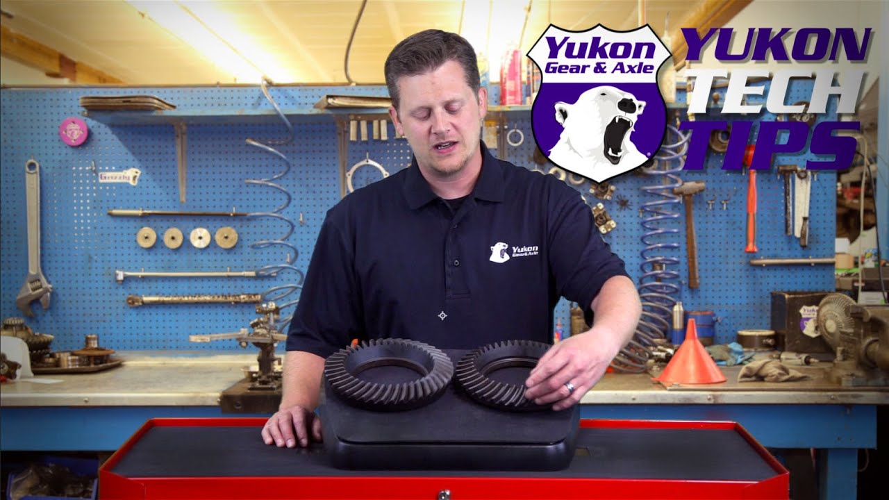
First, a diagram courtesy of Yukon Gear showing the anatomy of a ring gear (source: https://www.yukongear.com/blogs/how-to-create-read-ring-gear-patterns_1):

You must be registered for see images attach


I’ll end up using terms like heel/toe, drive/coast, etc. later on, so if you get lost, refer back to this diagram.

Here’s what mine looked like:

You must be registered for see images attach


Coast wear was pretty well centered, slightly favoring the toe (inner) side of the ring gear teeth. The drive side wear was similar, but definitely favored the toe side of the teeth. Overall, no chipped teeth, and nothing to suggest that they got overheated at any point during their life.

And here’s a shot showing the GKN Visco Lok clutches:

You must be registered for see images attach


No real point to the picture other than to show you what it looks like, and to serve as a reference if you are trying to figure out what limited slip unit is installed in your housing. That’s what a GKN Visco Lok looks like.

Step 5. Measure total bearing preload.​

Flip the housing over, but be prepared for the rest of the gear oil to come pouring out. Grab your inch-pound, needle or dial-style torque wrench, your 1-5/16” socket, and a 1/4" to 1/2” socket adapter. Tip: when installing the pinion yoke holding tool (which can be done anytime), put the socket on the pinion nut first – this will allow you to easily center the yoke holding tool before you cinch it down to the yoke. The pinion yoke holding tool will stay in place throughout this process.

To measure the total bearing preload (pinion bearings + carrier bearings), spin the torque wrench around in one direction 3-4 full turns, and while you are still turning, take a reading. This takes a bit of practice since you’ll be trying to eyeball a moving target, but you’ll get the hang of it. What you do not want to do is to measure how much torque it takes to start the pinion moving – this value will be higher than the torque required to keep it rotating. You want the torque to rotate measurement to reflect what it takes to keep it rotating.

You must be registered for see images attach


The total torque to rotate for mine was about 22 inch-pounds, which was in spec for used bearings. This does not tell you the full story, though. I’ll get to that in a second, but there are a couple more things you need to check first.

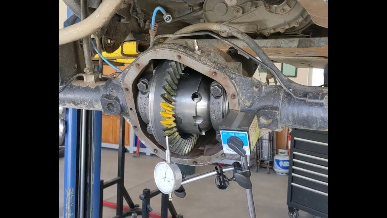
Step 6. Measure backlash and ring gear runout.​

Flip the housing back over (you’ll be doing this a lot).

Grab your dial indicator and all of the adapters needed to screw it into the differential housing cover bolt holes. As a reminder, all of the stuff needed to do that is listed in the Tools post above.

It’ll look something like this:

You must be registered for see images attach


I’ll add more details about exactly how to measure backlash and ring gear runout in my next post.

Backlash measured between 0.000 - 0.001”, which was WAY too tight. That explains why the wear favored the toe side of the tooth, and why the gears made so much noise, especially when they got hot. The correct spec is 0.004 - 0.006” according to the service manual.

To be clear, this differential had always made noise from the day I bought it with only 9,500 miles on the clock. So while drag racing didn’t do it any favors, I don’t think it was the cause. I’m guessing this differential somehow passed inspection, but probably shouldn’t have.

Ring gear runout isn’t all that important to note unless you intend to reuse your old gears. Mine measured 0.001”. Max runout spec from the manual is 0.002”, so this was good.

Step 7. Note carrier bearing cap markings.​

This step is critically important.

The carrier bearing caps are marked to show which side they go on as well as their proper orientation. The caps must go back exactly as you found them during reassembly. This is why you had to remove the RTV from them in Step 3.

To keep them from getting mixed up, the factory stamped letters on both the housing and the caps. For mine, they used the letter “L”. Note where it is marked on the cap, and how the letters are clocked on both sides:

You must be registered for see images attach


As oriented, the L’s on the driver’s side of the case and driver’s side carrier bearing cap are upside down. The L’s on the passenger’s side have both been rotated 90 degrees counter-clockwise.

Hopefully you can see how they made this idiot-proof – as long as the letters face the right direction on both sides, the caps are in their correct spots and orientations.

Step 8. Remove the carrier.​

Now that you’ve noted the carrier bearing cap markings, you can remove the cap bolts. They take a 19 mm 6-point socket to remove:

You must be registered for see images attach


Set the caps and bolts aside. Both will be reused.

The carrier + ring gear are wedged in the housing pretty good. If you are going to use a case spreader to help get it out, now is the time to grab it. I opted for the quicker/easier method of using a 3/4" box-end wrench slid on one of the ring gear bolts to act as a pivot against the housing, like this:

You must be registered for see images attach


All you have to do is rotate the yoke, and the carrier will pop itself up to the point where you can grab on to the ring gear and yank it the rest of the way out. You may need to go at it with a pry bar as well, but it will come out. Tip: the box end wrench and/or pry bar will start making marks in the differential housing after you do this a few times, so put something like a piece of leather between the wrench (or pry bar) and the aluminum case to prevent that from happening. I used part of an old leather belt (not pictured).

Set the carrier aside for now.

Step 9. Measure the carrier bearing shim thicknesses.​

The carrier bearing shims just sit in there…during the process of pulling the carrier out, yours might have fallen in to the housing. Do your best to keep track of which one went on which side, as this will be your starting point for setting both the backlash and carrier bearing preload for your new setup.

Pull out your micrometer, measure both, and write them down:

You must be registered for see images attach


Mine measured:

Driver’s side carrier bearing shim – 0.1305”
Passenger’s side carrier bearing shim – 0.1340”

Step 10. Measure pinion bearing preload.​

Flip the housing over, and grab your inch-pound torque wrench and pinion nut socket. You are measuring the preload again, but this time it will obviously only be your pinion bearings.

Mine, including the pinion seal, measured about 8 inch-pounds.

The pinion seal adds about 3 inch-pounds to the measurement due to friction, so we’ll call the pinion bearing preload about 5 inch-pounds, which is out of spec. The service manual calls for pinion bearing preload of 10-20 inch-pounds of torque to rotate for used bearings.

This also told me something else that was very important – the carrier bearing preload was too tight. If you’ll remember, the total preload measured in Step 5 was around 22 inch-pounds of torque to rotate. 22 minus 8 gives us 14 inch-pounds of carrier bearing preload. At face value, this seems fine, but carrier bearing preload has to take into account the torque multiplication factor of the gears installed.

Since these were 3.07 gears, 14 inch-pounds multiplied by 3.07 gives us 42.98 in-pounds of carrier bearing preload, which is way too high. For 3.07 gears, you’d want the actual value to be between 3 – 6.5 inch-pounds of added torque to rotate (as in, added to the pinion bearing preload number) to be within the factory bearing preload specs of 10-20 inch-pounds of preload. Hopefully that makes sense.

Stated another way, the preload specs should have been between 10-20 inch-pounds for the used pinion bearings by themselves. Total preload (pinion + carrier bearings fully installed) should have been 13-26 inch pounds, plus another 3 inch pounds to account for the pinion seal friction.

The carrier bearings did not appear to be any worse for the wear, so even though they were too tight, they still seemed to look okay with about 15k miles on the clock. I would not have expected them to last for a long time (like 100k+ miles), though.

Step 11. Remove the pinion nut, yoke, seal, oil slinger, and pinion gear.​

Time to remove that pinion nut. If you try this by hand, good luck. I used my 1/2" breaker bar plus my custom 3-foot cheater that went on the pinion yoke holding tool, and I was not able to get the nut to budge. My Milwaukee 1/2" impact zipped it right off though. Toss the nut – you won’t be reusing it. Set the old pinion nut washer aside – you won’t use it during final assembly, but you can use it during your initial setups so you can keep your new washer pristine for final assembly.

A couple taps from underneath the pinion yoke holding tool was enough to remove the yoke. Set this aside for now.

You can remove the pinion seal next. There is a notch in the seal to help with this. See picture below. Note the spider eggs – this also happened to Bryan (cowger’s), which I found amusing. Guess I need to drive the car more to keep spiders from wanting to nest there.

You must be registered for see images attach


Using either a flat head screwdriver or a chisel of some sort set in the notch, you can collapse the seal by hammering it in towards the center enough to allow you to get a small pry bar underneath to remove it. Clearly you won’t be reusing this, but take care not to damage the differential housing in the process of getting it out.

Once that is out, you’ll see a large black flat washer – this is the oil slinger. You’ll be reusing this during final assembly, so set it aside, but don’t lose it.

With the differential housing snout still facing up, grab your 4 pound dead blow hammer and get ready to relieve some frustration. With your hand underneath supporting the pinion gear from inside the housing, give the snout a few sharp taps from the outside and the pinion will release from the outer pinion bearing. That’s why you need to support it from the other side…otherwise, it’ll go crashing to the ground (or worse, into your toes). It’s heavier than it looks.

Step 12. Remove the pinion bearing races/cups.​

This part of the project is not a delicate operation. In order to remove the inner and outer pinion bearing races/cups that are pressed into the housing, you’ll need two things:

1. A long punch
2. A sledge hammer

I did not have a long enough punch to reach through the inside of the housing to the back side of the outer pinion bearing race, or at least so I thought. After a brief bit of cussing at my lack of foresight, I finally looked at the Lisle 59400 bearing race driver set and realized that a long punch suitable for this task was included in the kit:


You must be registered for see images attach


This project was humbling to say the least…after I got done feeling like a ********, I got back to work.

Getting the races out takes some serious force, and is why I recommend a sledge hammer instead of the non-marring dead blow hammer that I used for everything else.

The process goes something like this: seat the punch on one side of the bearing race, and give it a few hard taps. Move the tap to the opposite side and give it some more taps. Keep moving the punch back and forth to keep the race moving out – if you don’t, it’ll get jammed in there pretty good. It took me a few minutes of hard banging to get each one out.

The differential housing where the outer race sits has a notch that you can use to put the punch on one side, as shown in the picture below:

You must be registered for see images attach


The inner race has no such notch, and there isn’t much of a lip to grab onto with the punch, but just keep moving the punch back and forth on the back side of the race while hitting it and it’ll come out too:

You must be registered for see images attach


Note the channel cast into the housing – oil gets slung up by the ring gear and into this channel to feed oil to the outer pinion bearing. Clever.

Step 13. Remove the old pinion and carrier bearings.​

Just about done here.

All that’s left to do is remove the inner pinion bearing pressed on to the old pinion gear. This is where the clamshell bearing puller comes in really handy. Grab the outer race you just removed from the case, and place it on the bearing cone. Put the bearing puller on top of this assembly, tighten everything down, and zip it off with an impact wrench. The clamshell puller pulls the bearing off by grabbing on to the bearing cage. This is not a very strong part of the bearing, which is why you need the outer race. The clamshell puller will force the cage + rollers up into the lip of the inner race, and the outer race provides support for the rollers from the other side. The even pressure applied by this tool is what keeps the bearing from being damaged during removal, which is a huge plus. The video linked above shows how to use this tool in great detail…watch it all the way through, and then watch it again. I highly, highly recommend this tool, even if this is the only differential you ever rebuild. It was well worth the added expense IMO.

Once that bearing is off, you’ll have access to the pinion bearing shim. Mine measured 0.048”…this will be the starting point for your new setup.

You can also remove the carrier bearings using the same clamshell bearing puller tool. There’s an adapter that allows you to do this already included with the kit. Again, watch the video…it has all the info you need.

The last thing you can do is remove the stub axle seals. I got these out with a small pry bar (not pictured).
 
OP
OP
Steve M

Steve M

Enthusiast
Joined
Dec 29, 2011
Posts
1,071
Reaction score
202
Location
Dayton, OH

Clean Up and Preparing to Run Gear Patterns​

Next up: cleaning, organizing, and taking care of the one-time install items that are necessary when setting up a differential. Most of these don’t have to be done in any specific order, so don’t read too far in to how these are ordered.

Step 1. Remove old RTV from case and cover​

This step is straight-forward, albeit time consuming. The tools required are a razor blade, 800-1000 grit sandpaper, WD-40, brake cleaner, and an air compressor.

Use the razor blade to get as much of the RTV off as possible. There will still be some left behind, which is where the sandpaper and WD-40 come into play.

The sandpaper + WD-40 method is something I learned many years ago from a gentleman named Tony Mamo – those that came from the Chevy LSx world like me will likely recognize the name. The first time I tried it, I liked the results, and have been doing it ever since. It is essentially wet-sanding, only using WD-40 instead of water to keep the sandpaper from getting clogged up with RTV. When the RTV has been removed, wipe everything down with brake cleaner.

An alternative method is to use gasket remover, but be very careful if you go this route. Gloves and safety glasses should be worn, because this stuff is nasty. I got some on my bare skin many years ago, and it burned. Holy shit was that painful. Haven’t touched the stuff since.

Note: there are 4 non-threaded holes in the differential case (circled in red below) that will have RTV in them that needs to be dug out:

You must be registered for see images attach


A quick before/after shot of the differential cover:

You must be registered for see images attach


Also make sure you blow out the threaded holes in the differential case with compressed air to remove any left over RTV, WD-40, and/or brake cleaner.

Step 2. Inspect mating surfaces for nicks/burrs​

As the title states, go over the differential case and cover mating surfaces, bearing cups, etc. and look for any nicks or burrs that catch your fingernail. Knock the bigger ones down with a file and finish them smooth with sandpaper.

Step 3. Inspect stub axle support roller bearings​

Spin the rollers around with your finger, and look for any obvious signs of damage and clean out any debris if necessary. If they are damaged or don’t roll smoothly, you’ll need to remove and replace these. Mine looked fine and rolled smoothly, so I left the originals in place.

Step 4. Organize your shims​

Grab a micrometer and measure all shims (carrier, pinion, and [optional] solid spacer). Use a black Sharpie and write the measurements directly on the shims to help keep things organized. Make a full list of all the different shim sizes you have on a sheet of paper for quick reference.

Step 5. Install pinion bearing cups/races​

The pinion bearing inner and outer cups (a.k.a. races) need to be pressed into the differential housing. I used the Lisle 59400 pinion bearing race driver set to prevent damaging them during this process.

There are two ways to do this:

1. Use the race driver with a hammer
2. Use the race driver with a hydraulic press

I opted for #1 since it wasn’t until much later in this process that I borrowed my friend’s hydraulic press.

Hammering in races is not a delicate process – it takes a substantial amount of force to drive them in until fully seated. Getting them started straight is probably the hardest part of the process. If they get cocked to one side and aren’t going in, you may have to punch them out and try again. You’ll know when they are seated by listening for the tone of the hammer ping to change (it’ll sound more solid when seated), and also by looking closely at the races from the front and back sides.

As a reminder, you’ll need a 2-11/16” (2.6875”) race driver for the outer (smaller) pinion bearing, and a 3-1/4” (3.25”) race driver for the inner (larger) pinion bearing. The pictures below show different views of what the correct size race driver should look like:

You must be registered for see images attach


You must be registered for see images attach


The driver should make contact with just the thin outer lip of the bearing cup/race.

This is what the incorrect size looks like:

You must be registered for see images attach


It would technically apply even pressure, but it would be pressing on the part of the race where the rollers ride. If that gets gouged up, you’ll have to replace it. Bottom line: use the right race driver set. The cheaper ones from Harbor Freight (and others available online) did not have the sizes needed to do the job properly.

The race driver set includes handles suitable for hammering/pressing:

You must be registered for see images attach


Before driving or pressing them in, oil both the outside of the cups and the differential housing to help them go in smoothly without damaging either the bearing or the housing. Set the cups/races in place, and start driving them in:

You must be registered for see images attach


If you opt to use a press, the process will look something like this:

You must be registered for see images attach


Knowing what I know now, I’d opt to press them in rather than hammer them in. Both processes certainly work, but the hydraulic press is probably the safest way to keep from damaging the cups/races.

The fully seated inner and outer pinion bearing races/cups will look like this:

You must be registered for see images attach


Step 6. Press on carrier bearings​

The carrier bearings are pressed on first. These will stay in place throughout the gear pattern checks, and will be used during your final assembly assuming you don’t damage them at any point during the pinion depth setting process.

As a reminder, oil the inner race and carrier surfaces prior to pressing the bearings on to prevent damage:

You must be registered for see images attach


Yes, I did this step in a parking lot. My friend brought his press in the back of his truck so we could press the bearings on after work one day. It’s a bit of a haul up to his place, so it was nice to be able to split the difference by meeting up at work. He offered to let me take it home that same day and keep it for a while – in hindsight, that would have been a good idea.

Step 7. Prep ring gear​

Before installing the ring gear on the carrier, take a flat file and run it across the back side of the ring gear to knock down any edges that could be left over from the machining process. Dana Spicer did a good job – there weren’t any nicks or burrs sticking up that would have mattered. Still, this needs to be done to ensure the ring gear seats perfectly flat against the carrier…if it doesn’t, your setup will be all sorts of wonky. Thousandths of an inch matter, so don’t skip out on this part.

Step 8. Install ring gear​

The ring gear is intended to fit tightly around the carrier. Although I didn’t take any measurements, I’d suspect it is an interference fit, but certainly not a press fit.

To make things a bit easier, bake the ring gear in the oven to get it to expand a little. Make sure you clean off all oil with brake cleaner and dry it thoroughly before baking it, or your spouse may not be happy with you. I baked mine in a foil pan at 200 degrees F for about 30 minutes.

You must be registered for see images attach


While the ring gear is baking, clean and prep the new ring gear bolts. The new bolts are oiled before they are packaged to prevent rust. Oil and Loctite don’t exactly go together, so grab your favorite brake cleaner and start spraying. This is what came off of mine:

You must be registered for see images attach


I love small glass mason jars for stuff like this – brake cleaner doesn’t affect them, allowing you to douse the bolts thoroughly.

Pull the ring gear bolts out of the brake cleaner and dry them off with compressed air.

By this time, your ring gear should be nice and toasty. Pull it out of the oven, take it out to your work space and put it on the carrier (gloves highly recommended). It should slip on pretty easily – if it is still a little tight, pull it on the rest of the way with a couple of ring gear bolts.

Once seated, clamp the carrier + ring gear in a vise. As always, use something to keep your vise from marking up/damaging the carrier. Apply red Loctite to the ring gear bolts and tighten in an alternating pattern:

You must be registered for see images attach


The service manual torque spec for these bolts is 90-110 ft-lbs. I torqued mine to 100 ft-lbs, marking each on the carrier with a black Sharpie when they were fully torqued to spec.
 
Last edited:
OP
OP
Steve M

Steve M

Enthusiast
Joined
Dec 29, 2011
Posts
1,071
Reaction score
202
Location
Dayton, OH

The Basic Gear Pattern Setup Process​

This is where the repetition starts. If you are lucky, you may only have to go through this a few times at most, but unfortunately, this is where experience matters. Had I known what I was doing, or more to the point, what I was looking at when it came to interpreting gear tooth contact patterns, I could have drastically cut down on the number of setups it took me until I got to the final set of shims that got me to the correct backlash, carrier bearing preload, and perfect pinion depth for my new gear set.

This video is short and to the point (and amusing), and will give you a good idea of the basic process:


I’ll expand on this process with additional details below, but try to keep it to the point.

Let’s get started.

Step 1. Select a pinion shim​

Since I was rebuilding my OEM differential, I already had a starting point for setting the proper pinion depth. If you are building one from scratch and don’t have the specialty tools required to set the exact pinion depth ($$$), just pick something in the 0.035-0.054” range and give it a whirl. For my first setup, I reused the original 0.048” thickness pinion shim. As a reminder, this shim goes under the inner pinion bearing before you press it on. If you are using a setup bearing, slide the shim on and then slide on the setup bearing. Write down what shim you are using on a sheet of paper, and keep the paper handy – you’ll be making lots of notes during this process. Step 1 complete.

Step 2. Install pinion gear, bearings, yoke, etc.​

This step is a bit of a juggling act, but once you’ve done it a few times, it goes pretty quick.

Before installing anything, oil everything. Bearings (cups and cones), shims, etc. Anything that spins or that you’ll be driving in place needs oil on all surfaces. Transfer pipettes come in handy for applying oil: https://www.amazon.com/Plastic-Transfer-Pipettes-Graduated-Pack/dp/B005IQTSE0 I had a bunch that I’ve kept around for years that I dug out for this project, and I’m glad I did – it really helped to get the oil where it was needed without making a huge mess in the process.

Here's the basic process for installing the pinion:

- Orient the differential housing with the snout facing up
- Maneuver the pinion gear (with shim and inner pinion bearing installed) so that you can feed it up through the snout from the bottom. Once it is poking through the snout of the housing, slide on the outer pinion bearing, yoke, washer, and setup pinion nut (the non-locking pinion nut I told you to buy) in that order and engage the first couple of threads on the shaft. Once the nut is started, you won’t have to worry about the pinion falling out. My yoke slid on pretty easily by hand – if yours doesn’t, just give it a few taps with a dead blow hammer to get it started.
- Important note #1: you will not be using either a crush sleeve or solid pinion spacer for this part. You’ll be setting the pinion bearing preload by hand. Again, NO SPACER between the pinion bearings.
- Important note #2: you do not need the oil slinger
- Important note #3: you do not need the pinion seal installed. It would be in the way of everything if it was.
- Tighten the setup pinion nut down with your 1-5/16” socket and a 1/2" drive ratchet by hand until you feel slight resistance. Tightening the nut will drive the yoke down, which will in turn drive the outer pinion bearing onto the shaft. This should not be hard to do – the outer pinion bearing is an interference fit, and should slide on with firm, but not excessive force. The yoke should spin freely at this point (i.e. no pinion bearing preload).
- Tap the pinion from both the underside and from the top with a dead blow hammer to make sure the bearings are seated in their cups.
- Tighten the pinion nut a little more by hand until you feel rotating resistance. Measure your pinion bearing preload. Aim for 10-15 inch pounds of torque to rotate. It does not need to be tightened to spec – it just needs to be tight enough to prevent any play in the pinion gear. Do not use an impact wrench. If you overtighten the pinion nut, you can flat spot the bearings due to not having the crush sleeve/solid spacer in place.

Step 3. Select your carrier shims​

This one is a bit more of a guessing game. If your differential had the right amount of backlash and carrier preload, you can start with the carrier shims that came out of your original setup. If it is like mine was, you’ll have to adjust a little. I started with a 0.126” carrier shim on the left (original was 0.1305”) and a 0.1340” carrier shim on the right (same as the original) to try and open the backlash up a bit.

Apply some oil to the shims so they’ll stick to the sides of the case, and set them in place. Write down what shims you used and on which side they went.

Step 4. Install the carrier​

Oil the carrier bearing cones and cups along with their mating surfaces in the differential housing so they’ll slide in place easily (and without damage). This is another juggling act, so patience is required. Place the cups on the carrier bearings, and pick up the carrier while holding everything together as best you can. Gently wiggle the assembly into position between the carrier shims in the case. This is easier said than done due to the weight (~30 pounds) and the fact that the bearings are coated in oil. If something is out of whack, take it out, set it down, reposition, and try again.

If the carrier slides in place easily, there’s not enough carrier bearing preload, and you’ll need to try thicker shims. Ideally, you should need to tap it in place with a few strikes of a dead blow hammer. This is where the heft of the 4-pound dead blow hammer I recommended above comes in handy. Once everything is seated, use a small block of wood set against the carrier bearing cups and give each a firm tap with a hammer to make sure they are fully seated in the housing. Use a blunt chisel (or something similar) set against the carrier shims and give each a tap to make sure they are also fully seated.

Step 5. Install carrier bearing caps​

Oil the carrier bearing caps and set both in place, ensuring they are on the correct side and facing the right way (reference the stamped letters on the caps and case). Install the bolts and torque to 30-35 foot-pounds of torque (about half of the service manual spec). These do not need to be torqued to spec, and shouldn’t be during this process – the threads in the case are aluminum, and you don’t want to take the chance of messing them up by repeatedly tightening and loosening the bolts to the full torque spec. The important part is that they are held firmly in place so that nothing falls out or moves around – 30 foot-pounds of torque fulfills these requirements.

Step 6. Measure initial backlash​

There will be another post dedicated to this task with detailed step-by-step instructions, including pictures.

The factory service manual backlash spec is a relatively narrow range: 0.004-0.006”.

If the measured backlash falls outside of that spec, you’ll have to pull the carrier and repeat steps 3-6 with a different set of carrier shims until it does fall within spec.

Do not proceed to the next step until the backlash is correct.

Step 7. Measure total bearing preload​

Flip the case over and measure the bearing preload again. Assuming you measured the pinion bearing preload, you should aim to add about 6 inch-pounds of additional torque to rotate to that value. The value isn’t critical at this point – you just need enough preload so that nothing shifts around, which would lead to inconsistent backlash measurements and gear tooth contact patterns.

Step 8. Measure ring gear run-out​

Again, there will be another post dedicated to this task with pictures.

The factory service manual ring gear runout spec is 0.002”.

This step really only needs to be done once – unless you are doing something seriously wrong, this value shouldn’t change from setup to setup.

If the runout is more than this value, either the ring gear is defective, or you didn’t seat it properly on the carrier. Either way, stuff will be coming apart until you figure out what’s going on, including the possibility of needing a new ring and pinion and/or carrier.

Ring gear runout on mine measured no more than 0.001” – good enough for me.

Step 9. Paint the gear teeth​

Paint 3-4 ring gear teeth on both the drive and coast sides. Ideally, you’ll want to do this in 2-3 different locations around the ring gear to ensure consistency since each tooth is slightly different.

If your ring gear runout is in spec, I found that painting 3-4 teeth in one location on the ring gear is sufficient, and will speed up the clean-up process between setups.

Step 10. Rotate the ring and pinion to generate the gear tooth contact pattern​

Yep, there will be another post dedicated to this step too. I’ll detail how to get consistent, easy-to-read gear tooth contact patterns. I tried many different methods, and came up with one that is easy to implement and gave good, consistent results every time.

Step 11. Interpret the pattern​

The gear tooth contact pattern will tell you pretty much everything you need to know about whether or not your pinion depth is correct. It will either be too deep (i.e. pinion gear too far in toward the ring gear centerline), too shallow (i.e. pinion gear too far away from the ring gear centerline), or just right. This is part art, part science.

Again, I’ll make a post dedicated to this task for both aftermarket 5-cut and OEM 2-cut gears (and how to tell which ones you have). The Dana Spicer gears I used were 2-cut gears, so most of the information available on the internet was useless for interpreting my gear patterns. I learned this lesson the hard way so you don’t have to.

My first contact pattern results for reference:

You must be registered for see images attach


This drive side pattern says “too deep”. Way too deep. No need to even look at the coast side. Thinner pinion shim required.

Step 12. Disassemble everything​

Regardless of what your gear pattern told you, you’ll be pulling everything apart for cleaning. Carrier bearing cap bolts and caps come out first, the carrier next, and then the pinion. After you remove the pinion nut, washer, and yoke, the pinion will still be held in place by the outer pinion bearing. Just give the snout a few smacks with your dead blow hammer and it’ll come out (but be ready to catch it), leaving the outer pinion bearing behind.

All the gear marking compound needs to come off. It cleans off easily enough with brake cleaner, but it takes a while to get it off all of the individual ring and pinion gear teeth. If you don’t get the gear marking compound off, it’ll make reading your next gear pattern much more difficult, if not impossible.

The next steps you take, however, do depend on what the gear pattern told you. If everything looks good and everything is in spec, you are ready to move on to final assembly. If not, you’ll start back at step 1 and do it all over again until it is.

Summary​

The first time you do this will probably take about 2 hours, maybe longer depending on how good your guess was on the first set of carrier shims. It will go faster once you get the hang of it, but you should still expect each setup to take about an hour, and those hours add up fast. Patience is required – if you don’t get this right, you’ll either end up with gear whine or a differential that destroys itself.

Take lots of pictures and lots of notes. Document, document, document. I had two pages of hand-scrawled notes by the time I was done:

You must be registered for see images attach


You’ll get the hang of how everything works and what kind of adjustments you need to make to fix any measurements that are out of spec. In general, changing the pinion depth will affect your backlash, so a large change in the pinion shim thickness will generally require a similar magnitude of changes in your carrier shims. For reference, large changes in pinion depth are in the 0.008-0.010” range; small changes are in the 0.001-0.002” range.

Consistency is also required. If you don’t follow the steps laid out above consistently, you’ll end up chasing your tail during this process, which is what happened to me. Again, I’ve learned things the hard way so you don’t have to.
 
OP
OP
Steve M

Steve M

Enthusiast
Joined
Dec 29, 2011
Posts
1,071
Reaction score
202
Location
Dayton, OH

Measuring and Adjusting Backlash​

Backlash is one of the many critical measurements that needs to be made when setting up a ring and pinion in a differential.

Backlash is simply the amount of play between the gear teeth of the ring and pinion. During normal operation, the differential heats up due to friction. Heat causes the gears to expand – having the proper amount of backlash between the gears allows for this expansion, and also allows the gear oil to work between the teeth to help prevent wear and keep them within their proper operating temperature range. Too little backlash can cause excessive heat build-up as the teeth get jammed together due to expansion, which in turn squeezes the gear oil out. At a minimum, the gears will be noisy. Too much heat build-up can cause the oil to break down, ultimately leading to metal-on-metal contact that results in excessive wear and permanent damage to the gears and/or bearings. Too much backlash is equally bad - the gears will likely be noisy (whirring, roaring, and/or clunking), and could also be damaged during operation as the gear teeth slam back and forth against each other during acceleration/deceleration. In either case, you’ll be looking at another rebuild. Good for experience; not so good for your wallet.

The amount of backlash required is a function of the differential design and gear manufacturing process. The backlash spec range for the Viper’s Dana Super 44 using OEM 2-cut Dana Spicer gears is 0.004-0.006” (source: 2008-2010 Viper Service manual provided by 13COBRA). For aftermarket gears, I’ve seen specs anywhere from 0.006-0.012”. If in doubt, call the gear manufacturer (or for the Viper, Unitrax). For some gear sets, it may even be scribed somewhere on the ring or pinion gears. If all else fails, here is another resource that will give you a backlash spec starting point for aftermarket 2-cut gears, but I can’t verify the accuracy of the information: https://www.differentials.com/wp-co...rket-2-Cut-Ring-Pinion-Setup-Instructions.png

Measuring backlash requires a dial indicator gauge and a little bit of patience. It’s a little awkward at first, but once you get the hang of it, it’ll go pretty quickly for each setup you try. The most important thing is consistency – making sure the dial indicator is stable is paramount, followed by making sure the pinion gear cannot move during your measurements. That’s why I spent so much time and energy putting together something that allowed me to screw the base of the dial indicator’s adjustable arms directly into the aluminum differential case. If the dial indicator setup is allowed to move at all, you will not get consistent results. The same can be said for pinion rotation – any amount of pinion rotation during backlash measurements will lead to inconsistencies.

In order to get good, repeatable measurements, you need to make sure the plunger of the dial indicator sits square against the drive side heel of the ring gear tooth being measured in the plane of rotation. It’ll look something like this:

You must be registered for see images attach


Once the adjustable arms and dial indicator are set, hold the pinion gear tight - that’s why you see my makeshift breaker bar jammed against my tool box. Grab the ring gear with your hand, and gently rock it back and forth. Assuming you have any amount of backlash, you’ll hear a nice “click clack” as the drive and coast side of the ring and pinion teeth make contact with each other. Most dial gauges can be zeroed out, but you don’t need to bother doing that here – all you need to do is watch how the needle of the dial indicator sweeps back and forth. As an example, if the needle moves back and forth across 5 tick marks on the dial indicator, you have 0.005” of backlash.

Here's the important part: you won’t be taking just one measurement. Each tooth of the ring and pinion gears is machined slightly differently, so it stands to reason that the backlash measurements will also vary slightly as different teeth are engaged. You’ll want to take at least 10 measurements at different teeth around the ring gear to get an average backlash measurement. If you are *********, you’ll measure every other ring gear tooth. What you are looking for are any outliers – ideally, you want all backlash measurements to fall within specification, with the highest and lowest readings varying no more than 0.002”. If they vary more than that, it could be indicative of problems with how the gears were machined, or with the differential case itself. More than likely, though, it’s an issue with your gear setup and measurement process. As an example, not having enough pinion or carrier bearing preload would cause the gears to shift around as you are pulling on them, leading to inconsistent backlash measurements.

The carrier shims wedged between the carrier bearing cups and the differential case are used to adjust backlash on the Dana Super 44. As a reminder, the carrier shims also set the carrier bearing preload. The total carrier shim thickness (i.e., the left carrier shim thickness + the right carrier shim thickness) determines carrier bearing preload; the difference in thickness between the left and right shims sets the backlash. This diagram from the service manual will hopefully help:

You must be registered for see images attach


Again, this will be an iterative process. Acceptable carrier bearing preload covers a range, as does backlash – once you know approximately how much total shim thickness gives the desired bearing preload, you’ll try to keep that value constant as you swap shim thicknesses left-to-right to get the backlash within spec. After a few setups, you’ll have a pretty good feel for what adjustments are needed to find that sweet spot. If you can’t seem to get there with the shims you have, you’ll need to order more until you do. Thousandths of an inch matter, and it’s worth doing right the first time. Anything less than within spec is not “good enough”.
 
OP
OP
Steve M

Steve M

Enthusiast
Joined
Dec 29, 2011
Posts
1,071
Reaction score
202
Location
Dayton, OH

Measuring Ring Gear Runout​

This one will be quick.

Checking ring gear runout requires the same tools as above (dial indicator gauge), only instead of putting the plunger against the ring gear teeth, you’ll be placing it against the back side of the ring gear. There’s a small lip you are aiming for – it doesn’t really matter where you catch it as long as the dial indicator gauge is perpendicular to the back side of the ring gear and the plunger can move freely. It should look something like this:

You must be registered for see images attach


Once the gauge is set, all you have to do is rotate the pinion gear by hand and watch the needle. It’ll fluctuate a little as the ring gear rotates around – what you are looking for are the highest and lowest values the needle sweeps across.

The service manual spec calls for no more than 0.002” of runout. As long as you are below that number, you are good to go. Mine measured 0.001” for both the OEM setup as well as this new one.

If your ring gear runout measures outside of this spec, you’ll need to figure out why. Here are some possible causes:

1. Burrs on the back side of the ring gear
2. Burrs on the carrier mating face (i.e., where the ring gear seats)
3. Ring gear not seated properly
4. Ring gear bolts not torqued properly
5. Improperly machined ring gear
6. Warped ring gear
7. Improperly machined carrier
8. Warped carrier
9. Improperly machined differential case
10. Warped differential case
11. Not enough carrier bearing preload
12. Not enough pinion bearing preload
13. Carrier bearings not properly seated
14. Carrier shims not properly seated
15. Loose carrier bearing caps

As long as you are using quality parts, do the proper prep work (e.g., deburring the ring gear with a file), and follow the procedures outlined above in the Basic Gear Pattern Setup Process, I wouldn’t anticipate any issues meeting the ring gear runout spec. Again, unless you are doing something wrong, this value shouldn’t change, so once you measure it (assuming it's within spec), you shouldn’t have to do it again.
 
OP
OP
Steve M

Steve M

Enthusiast
Joined
Dec 29, 2011
Posts
1,071
Reaction score
202
Location
Dayton, OH

How to Get Easy-to-Read Gear Patterns​

If you only pay attention to one thing in this lengthy thread, this is it.

Get this part wrong, and you’ll be chasing your tail endlessly trying to figure out if your pinion depth is correct. This is the voice of experience speaking, so for the love of God and all that is holy, please listen.

Leading up to this project, I spent hours scouring the internet searching for differential setup advice, tricks, tips, and general wisdom. It seemed like those struggling the most with ring and pinion setups were having issues interpreting their gear patterns. The pictures they posted told the story, and it was usually quite confusing - for the most part, you couldn’t tell what was going on. There were no clearly defined areas that showed where the gears were making contact; it just looked like some paint had been smudged around, and that was about it. If you can’t see clearly defined patterns on the ring gear teeth where the paint was rubbed off by the pinion gear teeth (which will be where they primarily made contact), you won’t be able to tell what adjustments need to be made to get your pinion depth set exactly where it needs to be.

There’s no shortage of advice on how to do it correctly – YouTube, internet forums, aftermarket differential parts supply websites, take your pick. I tried a few different methods, and came up with one that worked for me. The key here is repeatability – when you find something that works, you need to do it exactly the same every time or you’re gonna be in for a long weekend (or 6, as was the case with my rebuild).

Here’s my advice on how to do it “right” – again, not an expert, so take it or leave it as you see fit, but if I had known the information I’m about to share with you, it would have saved me many, many hours of aggravation and the fitful nights of sleep that came along with it.

Step 1. Use the correct gear marking compound​

The master install kit that came with my gears did not include gear marking compound. I’m not sure why it didn’t, but you will definitely need it. I had some white gear marking compound in my stash of random car stuff that I had purchased from Summit Racing many, many years ago. It was still good, so I decided to start with that. Some folks raved about GM’s gear marking compound (https://www.amazon.com/ACDelco-10-5055-Gear-Marking-Compound/dp/B007Q10TES) – AC Delco part number 1052351, referred to as GM Original Equipment 10-5055 Gear Marking Compound. I’ve also seen AC Delco part number 1152615 associated with the same product. Either way, it’ll come in a nondescript white tube with black letters, and the gear marking compound will be yellow. I tried it, but I didn’t find it to be any better than the generic Summit Racing stuff I already had. If you do buy some, one tube will have enough compound to run gear patterns all day every day until the end of time. Okay, maybe not that many, but a little bit goes a long way with this stuff.

Proper gear marking compound will be hydrated ferric oxide-based, and will wipe off somewhat easily without smearing. You must use a color that contrasts well with the ring gear finish – Dana Spicer gears have a matte black-finish (as do most aftermarket gears), so white or yellow are good choices. I’ve seen others recommend Permatex Prussian Blue fitting compound (this stuff: https://www.amazon.com/Permatex-80038-Prussian-Fitting-Compound/dp/B000HBM86Q/), but I would not use this product unless I was installing REM treated gears, which have a highly polished finish. Otherwise, dark blue on matte black just doesn’t provide enough contrast to tell what’s going on, at least not easily.

Here's a free tip: I found that adding a small amount of gear oil (like a single drop) to a small amount of gear marking compound (like a good paint brush full) and mixing it well before applying it to the ring gear teeth really helps generate clearly defined gear patterns. The small amount of oil thins out the compound just enough to help it wipe off even more cleanly. Just don’t go overboard – you don’t want runny gear marking compound.

Step 2. Apply the gear marking compound​

Now you need a small paint brush, and a steady hand. I keep a pack of assorted paint brushes in my tool box for just such occasions, specifically these: https://www.walmart.com/ip/Assorted...Synthetic-and-Natural-Hair-25-Piece/193840762. I found that synthetic brushes worked the best.

Paint about 4 ring gear teeth on both the drive and coast side. Apply the compound so that it covers the teeth both evenly and completely - don't just glob it on. Done properly, it should look something like this:

You must be registered for see images attach


I found that wiping the compound off of the face (top land) of the ring gear teeth after painting them but before running the gears together helped me to see clearly where the wear pattern fell on the teeth between the face and flank, especially later on when I went back to look at the pictures I took of each pattern/setup to compare. And yes, you should take plenty of pictures (and label them!) to help you keep track of each setup you try.

Ideally, you’ll want to paint teeth at 2 or 3 different locations around the ring gear to ensure consistency and verify that you are doing things correctly. As I stated in one of my previous posts in this thread, however, I found this step to be overkill. As long as your ring gear runout is within spec and your backlash measurements have little to no variance (i.e., your backlash measurements for each setup are all within 0.001-0.002” of each other), you can probably get away with painting just one section of ring gear teeth. I’d still recommend painting multiple sections of ring gear teeth at least once, though, to prove it to yourself, especially if you get unexpected results.

Step 3. Apply load to the yoke​

This step is critical. If you don’t apply a load to the gears while you turn them, you will get misleading and/or hard-to-interpret gear patterns. And when I say “load”, that means you need to figure out some way to add drag to either the pinion or ring gear.

I’ve seen lots of suggestions on how to do this – wrap a shop towel around the yoke, wedge a piece of wood against the ring gear, jam a pry bar against the ring gear, use a leather glove against the ring gear, etc. If you are working on a differential that’s still installed in the car, you might even be able to apply the brakes while someone else turns the ring gear. That’s not an option with a Viper, so you can dismiss that one immediately.

I tried most of the suggestions above – here’s what I didn’t like about each:

- Shop towel around yoke: it applied drag, but it chewed up a couple of my shop towels in the process
- Piece of wood against ring gear: it applied drag, but it also chewed up the piece of wood, which left wood particles in the housing
- Pry bar against ring gear: I wasn’t able to find a way to do this without gouging up the aluminum differential housing
- Leather glove against ring gear: it applied drag, but it also chewed up my leather glove, which left leather particles in the housing

Something wrapped around the yoke seemed like the best option for applying drag without the possible drawback of leaving leather/wood particles in the housing. The last thing you want is foreign debris that gets into either the carrier/limited slip unit or the bearings, possibly both. But what could I use instead of a shop towel?

The best option I found was a 3/8" diameter, 15 ft. long piece of double braid nylon rope, available here: https://www.homedepot.com/p/Everbilt-3-8-in-x-15-ft-Double-Braid-Nylon-Rope-70682/205804734

It wraps around the yoke nicely where the yoke meets the dust shield, and it is super durable. The nylon is slick enough to still allow the yoke to spin under load, but strong enough that you can apply your entire body weight against it without fear that it’s going to break (working load limit is 370 pounds). It should look something like this:

You must be registered for see images attach


Step 4. Turn the RING GEAR​

This step is also critical.

Do not use the yoke to turn the ring and pinion gears. Yes, it is convenient, and yes, it certainly turns the gears, but doing so will not give you the desired results. And whatever you do, do not use a drill (or worse, an impact gun) to spin the yoke by the pinion nut. If you do, you risk overtightening the nut turning it one direction, which will in turn add too much preload to the pinion bearings (reminder: there’s no crush sleeve installed at this point); in the opposite direction, the pinion nut will come loose, which will in turn remove the required pinion bearing preload (reminder: we are using a regular nut for gear setups at this point instead of the prevailing torque nut required during final assembly).

You must turn the assembly using a 3/4" box end wrench on the ring gear bolts. Apply a load to the gears by pulling sideways on the nylon rope wrapped around the yoke (Step 3), and with your other hand, use a box end wrench on the ring gear bolts to turn the ring gear 4 full revolutions in one direction, and then turn it 4 full revolutions the opposite direction. You'll have to do this in increments since you can only access a few ring gear bolts at a time, but just keep turning it until you get there. This will give you the required drive and coast patterns ready for the dark art of interpretation. It should be a bit of a workout – it was about 90 degrees in my garage while I was doing this, and I was sweating bullets by the time I was done.

Below is an example of two gear patterns generated using two different methods to turn the gears. The picture on the left was made by turning the yoke, and the picture on the right by turning the ring gear. The same pinion and carrier shims were used for both setups, the same load was applied with the rope, etc. The only difference was turning the yoke vs. turning the ring gear.

You must be registered for see images attach


Both drive patterns shown used a 0.045” thick pinion shim. The picture on the left (made by turning the yoke) looks decent – maybe a bit deep, but the pattern is kinda centered face-to-flank. The picture on the right (made by turning the ring gear) tells a different story – the pinion is clearly too deep on the ring gear (the pattern is biased to the flank of the ring gear tooth). The added drag from turning the ring gear by the bolts made a significant difference.

And here is another example – same as above, only using a 0.042” thick pinion shim to help pull the pattern up out of the flank/root.

You must be registered for see images attach


The drive pattern on the left looks kinda okay, but I’m getting mixed messages; 3 teeth are telling me it may be a bit deep, and the other two teeth look pretty good. The picture on the right says we are pretty darn close – all teeth are saying “I wouldn’t go any shallower.” This is where we would need to reference the coast side for a second opinion.

I realize some of this probably doesn’t make sense, but give me a few more posts and I’ll try to explain why I was having so many issues interpreting these gear patterns, especially on the coast side.
 
OP
OP
Steve M

Steve M

Enthusiast
Joined
Dec 29, 2011
Posts
1,071
Reaction score
202
Location
Dayton, OH

2-Cut (Face Hobbed) vs. 5-Cut (Face Milled) Gears​

This little bit of info could have saved me so many headaches.

I’ve mentioned 2-cut vs. 5-cut gears throughout this thread, but until now I haven’t shown what the differences are, and more importantly, why it matters.

Here’s a pretty good description (source: https://www.differentials.com/two-cut-vs-five-cut-gears/, emphasis added is mine):

“The terms Two Cut and Five Cut refer to the machining process used to manufacture Ring and Pinion gear sets. Traditional ring and pinion gears were manufactured using a Five-Cut process (Face Milling). Most current manufacturing methods use a Two-Cut process [Face Hobbing] that only requires about 30% of the traditional manufacturing time. Each process results in a different gear tooth profile, and slightly different method for setup.

Here are a couple of pictures that illustrate the differences in the gear tooth profile:

You must be registered for see images attach


You must be registered for see images attach


Image sources:
https://www.differentials.com/two-cut-vs-five-cut-gears/
https://www.revolutiongear.com/2_cut_vs_5_cut_gears

And here is a video showing the two side-by-side:


Once you know what to look for, it’s pretty easy to tell the difference. Unfortunately, I didn’t know anything about this until I was over 10 hours into this little project.

Many OEM manufacturers, including Dana Spicer, have gone to the 2-cut machining process – a ~70% savings in manufacturing time is huge in a mass production environment, and there don’t appear to be any drawbacks in terms of durability or added gear noise (i.e., they are just as strong, and run equally quiet when set up properly).

The major difference between the two, and what really matters here, is that the gear patterns of a 2-cut vs. a 5-cut gear set look totally different. Revolution Gear hints at this when they state on their website “2-Cut Gears also have a natural "bias" condition; that is, the pattern shows up slanted when the pattern is rolled with gear marking compound.”

Huh?

Hang on…I’ll show you.
 
OP
OP
Steve M

Steve M

Enthusiast
Joined
Dec 29, 2011
Posts
1,071
Reaction score
202
Location
Dayton, OH

5-Cut Gear Pattern Examples​

I’ll try not to spend too much time here since the gears I used were of the 2-cut (face hobbed) variety, so most of this won’t apply to what I did.

Most gear pattern examples out there on the internet represent patterns for 5-cut (face milled) gears. With the proper pinion depth, you should see a nice oval pattern on both the drive and coast side of the ring gear teeth. It is important to note that the pattern may not be centered between the heel and toe of the tooth – as long as the backlash is correct, there really isn’t much you’ll be able to do about it. Here are examples of acceptable patterns (source: https://www.yukongear.com/blogs/how-to-create-read-ring-gear-patterns_1):

You must be registered for see images attach


Keep in mind that these patterns were run on new gears. If you are installing used gears, you may not be able to get a good pattern on the drive side since that will have the most wear. In that case, you’ll have to rely on the coast pattern to verify correct pinion depth.

If the pattern is too shallow, it’ll be too high up on the gear tooth. If it is too deep, it’ll look like it is coming up out of the root. Here are a couple examples showing both conditions from the same source referenced above:

You must be registered for see images attach


To fix a pattern that is too shallow, you’ll need to increase the pinion shim thickness and try again. If the pattern is too deep, you’ll need to decrease the pinion shim thickness.

Pretty simple, right? Especially now that you know how to generate easy-to-read gear patterns.

But there’s one more piece of information you can use with 5-cut gears to figure out whether or not your pinion depth is correct, and that is by interpreting the pattern that shows up on the pinion gear. I learned about this technique here: http://gearinstalls.com/

That website is the only place I’ve ever seen this technique mentioned. The pinion gear pattern you are looking at is essentially a comet, and you are specifically looking at where the comet tail falls on the pinion gear tooth. This is what I’m talking about (circled in black and shaded slightly red in the right picture for emphasis - source: http://gearinstalls.com/):

You must be registered for see images attach


The important thing to note is that the comet tail pattern will be opposite to what the ring gear pattern shows. If the ring gear pattern is too deep, the pinion pattern will appear too shallow. If the ring gear pattern is too shallow, the comet tail will appear too deep (it’ll be tucked into the root of the pinion gear). Ideal pinion depth will put the comet tail about half way between the center of the pinion gear tooth and the root. This picture should hopefully help explain the concept better than my words:

You must be registered for see images attach


And here’s just one example from that same website that puts it all together:

You must be registered for see images attach


In the top 3 pictures, the drive and coast patterns look pretty good, but the comet tail says it is too shallow. He added a little more pinion shim thickness, and ended up with the bottom 3 pictures which ended up being the final setup for those gears. The comet tail came out of the root on the pinion gear tooth and was feathering toward the center, which is about ideal. It should be noted that many installers will run the pinion slightly deep – that is preferred for heavy duty applications since heavy loads will try to pull the gears apart. If the gears are set up a little deep, it’ll still leave you with lots of tooth contact area under load (think towing something heavy with a truck).

If you want to learn a lot, peruse the Gear Installs website. It is mostly dedicated to Toyota products, but he deals with lots of different designs and challenges, and has pictures that show pretty much every step along the way. The guy that created and maintains that website is who ended up helping me out in my time of need – I sent him an email out of the blue when I got stuck, and he responded within a day. He was incredibly generous with his time and insights, ultimately helping me be successful with my little endeavor. I don’t know if he’ll ever see this post, but if he does, thanks Ken…you are a class act!

In summary, with 5-cut (face milled) gears, you have three sources of information to help you determine proper pinion depth:

1. Drive side pattern (ring gear)
2. Coast side pattern (ring gear)
3. Comet tail (pinion gear)

The drive side pattern is the most important, so if you can only get one thing right, focus on that one.
 
Last edited:
OP
OP
Steve M

Steve M

Enthusiast
Joined
Dec 29, 2011
Posts
1,071
Reaction score
202
Location
Dayton, OH

2-Cut Gear Pattern Examples​

Throughout most of this process, I thought my coast patterns were total garbage – I couldn’t tell what was going on. I didn’t even take pictures of most of them because they weren’t telling me anything useful (or so I thought). They weren’t centered, they weren’t oval…they were nothing like you see in the gear pattern charts available online. It was the same but not quite as bad on the drive side. I eventually started wondering if the gears were defective.

What most online resources failed to mention is that 2-cut gear patterns look nothing like 5-cut gear patterns, especially on the coast side. I could have saved hours (like double-digit numbers of hours) had I known this, and had I also known that the gears I had were of the 2-cut variety.

West Coast Differentials at least took a swing at it, but only provided this diagram as an example of a 2-cut gear pattern (source: https://www.differentials.com/two-cut-vs-five-cut-gears/):

You must be registered for see images attach


Not as helpful as they probably intended.

Yukon got a little closer to the mark with their diagrams (source: https://www.yukongear.com/web_images/pages/Brochures/2-Step-vs-5-Step-Gears.pdf):

You must be registered for see images attach


Note the term “bias”, also sometimes referred to as a “bias condition” or “bias pattern”. Basically, the pattern will look something like a parallelogram, or at least some sort of square-ish or rectangular-ish shape that is leaning over on both the drive and coast side.

The Yukon diagram shows ideal 2-cut gear patterns for both drive and coast.

Here’s the key to knowing when you are done: the ideal pattern will have face-to-flank symmetry.

What does that mean? Hopefully a few arrows and lines will help:

You must be registered for see images attach


The width of the ideal 2-cut gear pattern should be the same at the face (top part of the gear tooth) and the flank (bottom or base of the gear tooth). All you have to do is find the right shim thickness to achieve that.

If the pinion is too deep, the pattern will be wider at the base of the tooth and narrower at the top. If it is too shallow, the pattern will be wider at the top of the tooth and narrower at the bottom.

If it is way too deep, it’ll look similar to a 5-cut gear pattern – basically like the sun is rising up out of the root. If it is way too shallow, the pattern will do the opposite - it’ll look like the sun is coming down from the top of the tooth.

Based on my limited experience, the drive side pattern came in to focus more quickly and clearly than the coast side pattern. Once I got the drive pattern close, the coast pattern helped me make small tweaks to get it just right.

It is important to note than the comet tail (the pattern on the pinion teeth) is not a reliable indicator for 2-cut gear patterns, so you only have two sources of information to help you determine proper pinion depth:

1. Drive side pattern (ring gear)
2. Coast side pattern (ring gear)

If you still don’t understand, fear not; more pics are on the way.
 
OP
OP
Steve M

Steve M

Enthusiast
Joined
Dec 29, 2011
Posts
1,071
Reaction score
202
Location
Dayton, OH

Different Shim Combos and Results – Part 1​

Now it’s time for you to bear witness to my floundering.

Important Note: All of the patterns you are about to see were the result of using my custom-made setup pinion bearing.

This first set of drive side patterns was generated by turning the pinion instead of the ring gear like I should have done. As a result, the patterns were ill-defined and inconsistent:

You must be registered for see images attach


With the proper pressure applied to the yoke and by turning the ring gear by the bolts with a 3/4" box-end wrench, the 0.045” pinion shim went from being “Maybe Good?” to “Too Deep”:

You must be registered for see images attach


That is why you must follow each step laid out above in my “How to Get Easy-to-Read Gear Patterns” section.

And now you will start to see evidence of my lack of understanding of what I was looking at. The 0.042” thick pinion shim was just about right, but I was so confused by what I was seeing on the coast side that I ran thicker pinion shims instead, including the 0.044” thick shim twice:

You must be registered for see images attach


Clearly I was going the wrong direction, so I went back the other way with the pinion shims and came up with these:

You must be registered for see images attach


Keep in mind that each of these setups took about an hour, so that was a lot of time (and sweat) invested, much of which I could have saved if I had just known the secrets of reading 2-cut gear patterns.

At this point, I decided to go with the 0.043” pinion shim as the starting point for my final setup with a pressed-on inner pinion bearing. This would place the pinion slightly deep on the ring gear, which is generally preferred for gears that will be subjected to heavy loading.
 
OP
OP
Steve M

Steve M

Enthusiast
Joined
Dec 29, 2011
Posts
1,071
Reaction score
202
Location
Dayton, OH

Where My Setup Bearing Failed (And Why)​

To recap, I went through many different iterations with my setup pinion bearing (the one that just slips on and off without the need for a press), and decided to try the 0.043” pinion shim for what I thought would be my final setup.

I slapped on the 0.043” pinion shim along with my brand-new Timken inner pinion bearing, and into the press it went (along with my custom-made bearing press adapter/tool):

You must be registered for see images attach


You must be registered for see images attach


Bitchin.

Little did I know that I was in for a large serving of humble pie sprinkled with a bit of rage. Holy shit I was pissed.

The first clue that something was off was the backlash measurement. I previously achieved the proper backlash spec (0.004-0.005”) for a 0.043” pinion shim by using 0.129” left and 0.1315” right carrier shims. That same carrier shim combination with the pressed-on inner pinion bearing (and the same pinion shim) resulted in 0.001-0.002” of backlash. That was way tighter than I expected; in hindsight, I should have immediately known that the pinion was too deep on the ring gear.

I swapped out the left-hand carrier shim for one that was 0.126”, leaving the right-hand carrier shim the same (0.1315") – that gave me 0.004” of backlash. Tight, but within spec. I then proceeded to run the gear pattern and came up with this:

Drive:

You must be registered for see images attach


Coast:

You must be registered for see images attach


Well shit.

The pattern went from being slightly deep to definitely too deep.

Why?

This is my theory: the inner pinion race has to expand ever-so-slightly when the inner pinion bearing gets pressed on the pinion shaft – that’s what holds it in place. The tapered rollers consequently get pushed out as the inner race expands. That small change would ultimately affect how far the rollers seat into the matching tapered cup that is pressed into the differential housing; they would sit a bit proud, effectively pushing the pinion gear teeth toward the ring gear centerline, causing a deep(er) pattern.

What backs my theory is that with no other changes, the pressed-on bearing tightened up the backlash significantly, which is indicative of a deeper mesh. The pattern proved that it was indeed too deep. The results were also consistent and repeatable. Based on my previous findings (referencing the pics in the post above), I’d guess that the pinion was now about 0.003” too deep (it looks like the pattern generated with a 0.046” pinion shim in the post above).

Bottom line: was a setup bearing useful? Yes and no.

On the positive side, I was able to quickly swap out pinion shims without the need for a press or a clamshell bearing puller. That saved me at least some time, and I was able to gather a lot of good insights as to how each shim affected the overall setup. It was also consistent – I ran some shim combos multiple times, and the results with the setup bearing were the same each time.

On the negative side, I still had a lot of work ahead of me to find the correct pinion shim, but I was at least in the general ball park. Unfortunately, I now had to pull the bearing off and press it back in place without damaging it, which added a bit of stress since I only had one inner pinion bearing on hand.

Would I use a setup bearing if I had to do this over again?

Probably not.

It was good for a first-timer like me, but now that I have at least some experience, I’m not sure it would serve any purpose other than to get me within a few thousandths of the correct pinion shim thickness before whipping out the hydraulic press. If you'll remember, I did not have a hydraulic press on hand at the time (it was at my friend's house ~45 minutes away), so I was hoping I would only need it once. I've since learned that a hydraulic press is something you really need on-site throughout the entire process - don't fight it, just get (or borrow) one.

My recommendation also assumes that you can quickly and easily remove the pressed-on bearing without damaging it. It can be done, but you need the right tools on hand to do it (like a clamshell bearing puller). If you are reliant on a shop to do the pressing, a setup bearing would make a lot of sense, and would likely save you quite a few trips to and from the shop, but expecting it to be a one-and-done type of thing is probably unrealistic.

Your mileage may vary.
 
OP
OP
Steve M

Steve M

Enthusiast
Joined
Dec 29, 2011
Posts
1,071
Reaction score
202
Location
Dayton, OH

Different Shim Combos and Results – Part 2​

I took a few days off after that last round of disappointment, but it ended up being a good thing – it gave me a chance to clear my head and put a plan together to get the proper pinion depth with the pressed-on bearing.

Thankfully I already had the Mopar 0.040” – 0.044” Pinion Shim Kit (part number 04856369) on hand. The 0.043” shim was clearly too thick, so my plan was to try the 0.042”, 0.041”, and 0.040” shims and record the results. My clamshell bearing puller did a great job of removing the pressed-on pinion bearing without damaging anything, and the bearing went right back on with the 20-ton press (x3).

The results:

You must be registered for see images attach


Looks like the 0.040” pinion shim was the winner. I also sought out a second opinion from the gentleman that owns http://gearinstalls.com/, and this is what he had to say:

“Oh yeah....I like that one......winner! That represents the perfect 2-cut paint pattern there....both the position and the 'symmetry'.”

Here’s another look at the 0.040” shim results, with a couple of lines showing the symmetry to which he refers:

You must be registered for see images attach


Good enough for me.

I also asked if he preferred to run the pinion a little deep on the ring gear for better overall durability, and this was his response:

“In order to eliminate or greatly reduce any ‘noise issues’ with a lot of these super quiet late model Toyota trucks, I do aim for ‘exact depth’. Pretty much now stay away from too many of the ‘slight deep’ condition. The late model Tacoma gears, as an example, are sensitive to needing to be ‘exact depth’.....that's why a lot of them from other shops are noisy. They don't fine tune. But mine are quiet.”

Exact depth it is then.

In summary, I started with the original 0.048” shim, and ended with the 0.040” shim for this particular set of gears in this housing. For perspective, a sheet of standard printer paper is 0.004” thick. The difference between slightly deep and just right was 0.001”. That’s what I mean when I say the details matter – one-thousandth of an inch is less than the thickness of a human hair.

On to final assembly!
 
OP
OP
Steve M

Steve M

Enthusiast
Joined
Dec 29, 2011
Posts
1,071
Reaction score
202
Location
Dayton, OH

Final Setup/Assembly​

Time to up the pucker factor a little bit.

In theory, if your setup process is sound and you’ve been consistent, the final gear pattern generated should be exactly the same as what you just accomplished. There are some additional steps for final assembly, but if you’ve gotten this far, it’ll be nothing you can’t handle.

First, the service manual specs:

You must be registered for see images attach


Let’s dig in!

Step 1. Remove gears from housing and clean off any gear marking compound​

Remove the carrier bearing caps and bolts and set aside. Pull the carrier out of the differential housing and set the shims aside. Flip the housing over and remove the pinion. The pressed-on inner pinion bearing will stay in place this time – you’ve already found the correct pinion shim, so there’s no need to repeat any part of that process.

Clean off all gear marking compound from both the ring and pinion (I used brake cleaner). You’ll be running one final gear pattern check, and you don’t want any evidence of the previous pattern muddying the waters.

Step 2. Install output shaft seals​

If you need to install new stub shaft support bearings, now is the time to do it. I left mine in place throughout the process, so I didn’t touch them.

Turn the housing on its side, grab your new output shaft seal, set it in place, grab the installation tool(s) of your choice (I used the specialty Miller tool # C-4026B + a hammer), and tap it in place. A large socket might also be able to be used in place of the Mopar tool.

You must be registered for see images attach


The key is getting each seal started squarely – if it gets cocked to one side, it’ll make the seal hard to drive in place. It did take a fair amount of force to get it started, so don’t be afraid to do a little banging. That’s what I liked about the Mopar tool – the design protects the inner part of the seal from damage and ensures it is seated flush to the housing.

Once one seal is seated, flip the housing over and install the other.

This step can be saved until later in the final assembly process, but it is far easier to maneuver the differential into a more advantageous position without the carrier installed. The carrier + bearings + ring gear add a significant amount of unevenly distributed weight to the differential housing.

Step 3. Determine proper solid spacer shim stack (Optional)​

If you are using a crush sleeve, this step is optional. If you are using a solid spacer, this step is not optional.

The solid spacer instructions recommend installing all of the supplied shims as a starting point:

You must be registered for see images attach


If the solid spacer was machined correctly, you shouldn’t end up with any preload no matter how much you tighten the pinion nut with all of the shims installed. I thought I’d be able to skip this step and get a little closer to the mark by using the old crush sleeve as a starting point for the shim stack, but it ultimately did not help.

This is another iterative process, so just pick a shim combo and give it a whirl. Write down the shim combo in your notes. The assembly order is as follows: pinion, pinion shim + inner bearing (already assembled/pressed in place), the solid spacer, and then the solid spacer shim stack. As always, oil the bearings first. Install the assembly into the housing, then slide the outer pinion bearing and yoke on from the other side. Do not install the oil slinger or pinion yoke seal yet. Slide the setup washer and pinion nut on the pinion shaft and tighten until the yoke and bearing are fully seated.

Now for the moment of truth. Grab your torque wrench, and start tightening the setup pinion nut down. I started at 100 ft-lbs. Measure the pinion preload as you are tightening. If it is anywhere under 15 in-lbs of torque to rotate, tighten the pinion nut some more. I went up in 25 ft-lb increments. Check the bearing preload at every increment. If the shim stack is correct, you’ll likely start getting some preload as you start approaching 150 ft-lbs of torque on the pinion nut. If the stack is too thick, you won’t have any preload. If the stack is too thin, you’ll have too much preload right off the bat.

As an example, I started off with a 0.035” shim stack. I tightened the setup pinion nut to 100 ft-lbs, and was immediately greeted with 40 in-lbs of torque to rotate – way too tight. If that happens, back the nut off, pull the yoke and washer off, remove the pinion from the housing, and try a thicker solid spacer shim stack. I tried a 0.051” shim stack next, and had no preload even at 150 ft-lbs of torque on the pinion nut.

After a few more iterations, I settled on a 0.048” thick shim stack (0.012” + 0.016” + 0.020” shims). That gave me 0 in-lbs of preload at 100 ft-lbs of torque on the pinion nut, 8 in-lbs @ 150 ft-lbs, 22 in-lbs @ 200 ft-lbs, 24 in-lbs @ 220 ft-lbs, and 27 in-lbs @ 250 ft-lbs of torque. That’s right about where I wanted to be for the pinion bearings.

Important note: pinion bearing preload comes on FAST. It’ll be nothing, nothing, nothing, and then boom – it hits. Spicer states that a 0.001” change in preload spacer thickness will change the torque to rotate approximately 30 in-lbs (source: https://media.spicerparts.com/cfs/files/media/eCkmB4hg6u7qP3cyo/xmzz0551.pdf, pg. 15).

Once the preload is where you want it, remove the pinion nut, washer, and yoke and set aside. The pinion should still be held in place by the outer pinion bearing’s friction fit on the pinion shaft.

If using a crush sleeve to set the pinion bearing preload, this step is where you would install the crush sleeve.

Step 4. Install oil slinger​

You must be registered for see images attach


Step 5. Install pinion yoke seal​

Now is the time to install your brand-new pinion yoke seal. Put a small amount of oil on the seal’s o-ring and set it in place. You can either tap it in with a hammer, or you can use the Mopar specialty tool (Miller part # 8889). The tool clears the pinion shaft and fits into the seal’s channel, allowing you to apply even pressure to the seal with either a hammer or a press as you drive it in place, minimizing the risk of damage to either the seal or pinion shaft. I’d recommend running a small bead of RTV sealant just under the outer lip of the pinion yoke seal – that should keep any oil that gets past the o-ring from going any further.

You must be registered for see images attach


Step 6. Tighten pinion nut to spec while measuring pinion bearing preload​

Slide the pinion yoke on. I recommend adding a small amount of Teflon sealant to the pinion yoke splines before sliding it on to keep any oil from seeping past. If you do this, only apply sealant to the yoke splines – otherwise, you’ll drive sealant into the outer pinion bearing as the yoke slides down the splines.

Install a new washer and new pinion nut. I did not use Loctite on the pinion nut. In hindsight, it wouldn’t have been a bad idea. If that nut backs off at all, you’ll lose your pinion bearing preload, and bad things will happen.

Tighten the pinion nut in the same increments you used in Step 3 above and take note of the preload at each increment. The pinion yoke seal will add about +3 in-lbs to your readings, so keep that in mind. The pinion nut final torque spec is 220-280 ft-lbs. I tightened mine to 250 ft-lbs, and ended up at around 30 in-lbs of total preload (27 in-lbs bearings + 3 in-lbs for the seal). I recommend painting a torque stripe on the pinion nut and yoke to allow for quick and easy inspection during routine maintenance.

If you hear or feel any scraping as you rotate the yoke, it is likely the yoke dust shield making contact with the seal. To fix this, you can take a brass hammer and give the dust shield a few taps under the outer edge to bend it away from the seal. The dust shield is pretty thin, and can get bent during the gear pattern checking process.

If you are using a crush sleeve, I wish you luck. Again, preload comes on fast, so tighten with care. If you overtighten the crush sleeve, you’ll have to pull everything apart and try again with a new crush sleeve. Not the end of the world, but still a PITA.

Step 7. Install carrier and tighten bolts to spec​

Set the carrier bearing shims in place in the housing. Install the fully assembled carrier + carrier bearing cups in the housing, firmly seating all parts with a dead blow hammer. As always, oil the bearings and all mating surfaces prior to assembly.

Install the carrier bearing caps, double-checking the orientation of each. Install the carrier bearing cap bolts (takes a 19 mm 6-point socket) and tighten to 65 ft-lbs.

Step 8. Measure carrier bearing preload​

Flip the housing back over, and measure the total bearing preload. The carrier bearing preload should add approximately 6-10 in-lbs of torque to rotate. Mine added about 6-7 in-lbs. When multiplied by the gear ratio, that fell within the 15-35 in-lbs preload spec for new bearings, albeit on the lower end of that scale.

If there’s too much (or not enough) carrier bearing preload, you’ll have to adjust the shims to bring it into spec. As a sanity check, properly preloaded carrier bearings should require a few good whacks from a dead blow hammer to seat the carrier in the housing. Keep in mind that any changes to the carrier shims will affect your backlash measurements. If you add or take away shim thickness, make sure it is the same amount on each side to minimize the impact on backlash.

Step 9. Measure final backlash​

This will be your first sanity check that everything is where it should be. I took 10 different backlash measurements at 10 different locations around the ring gear. Most measurements were 0.005”, with one being 0.0045”, and one being 0.006”. All backlash measurements must fall within spec before moving on to the next step.

Step 10. Final gear pattern check​

This is it – the most stressful gear pattern you’ll ever run. If the backlash is in spec, there’s a good chance the pinion depth has not changed, and the gear pattern will be pretty much identical to what you ran before starting the final assembly process. My results:

You must be registered for see images attach


Stick a fork in it – that shit is done. The paint can stay on the gears – it will get washed off by the gear oil during break-in and removed during the first oil change.

Step 11. Install stub shafts​

Drive the stubs in with a dead blow hammer until the internal snap rings click:

You must be registered for see images attach


Step 12. Install drain plugs​

Install all 4 drain plugs with Teflon sealant:

You must be registered for see images attach


Step 13. Add oil (optional)​

You can skip this step until you get the differential back in the car; dealer’s choice. I opted to do it now because of the easy access. Filling the differential with oil while it is suspended from the work bench in this orientation ensures that the pinion bearings are well lubricated before your first drive. As a reminder, the outer pinion bearing only gets lubricated after the oil gets slung up and over by the ring gear, so giving it a little head start isn’t a bad idea.

I added 1.5L of gear oil to the housing – that should get you close to the proper fill level for a newly built (i.e. dry) differential.

Step 14. Apply RTV sealant​

Clean the sealing surfaces of the differential housing and cover with brake cleaner. Apply a 1/8” – 3/16” thick bead of sealant around all holes with a bead connecting all of the holes together:

You must be registered for see images attach


You’ll have about 10-15 minutes of working time (depending on the conditions) before the sealant starts to set. If it starts to set before you can get the cover in place, scrape it all off and start over. The master install kit that came with my new ring and pinion included Permatex Ultra Grey, so I used that.

IMPORTANT: You must apply sealant to the carrier bearing cap supports in the differential cover. This will bridge the gap between the supports and the carrier bearing caps.

You must be registered for see images attach


Note: If you did not add oil in Step 13, allow 24 hours for the sealant to dry before adding oil (as per Permatex’s instructions).

Step 15. Install Cover​

Carefully place the cover on the differential housing. Install 9 differential cover bolts finger-tight. Tighten bolts in a criss-cross pattern to 35 ft-lbs. The bolt heads require a 13 mm 6-point socket.

Tip: I bought a couple of double-ended M10 x 1.5 threaded studs (https://belmetric.com/m10-double-ended-stud-din-835-class-8-8-steel/?sku=S10X70DYLW) to act as alignment dowels for this step. Once the cover is on and held in place by a few hand-tightened bolts, you can take the studs out and replace them with the proper bolts. This method will prevent the cover from moving around during the tightening process, ensuring the RTV sealant makes a good, continuous bond. If you move the cover around too much, you may end up with a leak path. If that happens, you’ll be pulling the entire differential from the car to try again, so getting it right the first time is essential.

You must be registered for see images attach


Time to take a little breather – the hard work is done, but there’s still some heavy lifting required to get everything back in the car. I’m not going to provide a step-by-step on how to do that part, as that’s been covered at length in other threads on this and other forums. If you have any questions, though, just ask.
 
OP
OP
Steve M

Steve M

Enthusiast
Joined
Dec 29, 2011
Posts
1,071
Reaction score
202
Location
Dayton, OH

Break-In​

I finished rebuilding this differential on September 11th. I didn’t get to go for the first drive until October 4th.

The reason? A poorly machined Driveshaft Shop (DSS) heavy duty axle flange.

Story time: In order to remove the differential from the car, you have to pop the axle flanges off of the differential output stubs. The axle flanges are retained by circlips on the stubs. The circlips are compressed during the process of sliding the axle flanges in place; once they are at the proper depth, the circlips spring back into grooves machined into the female splines of the axle flanges, effectively locking the axles in place on the inboard side. In order to remove them, the circlips must release, but that requires the proper machine work on the flange’s female splines – otherwise, the circlips won’t compress, and if they won’t compress, they won’t release. One of my DSS axle flanges refused to release, and it took one of my OEM stubs hostage in the process. Unfortunately, this is not the first time this has happened to me.

Thankfully, you can just unbolt the DSS axles from the flanges. This design allows you to still be able to get the differential out, but I also needed to be able to remove the stuck flange from the stub. The OS Giken uses completely different stubs compared to stock, and you can’t use the DSS axles without both flanges (the other one came off easily enough).

The removal process didn’t work out so well. I beat on the offending flange for hours with a slide hammer and my custom steel adapter plate to no avail. I finally ended up putting the assembly in my bench vise and gave the stub shaft a few gentle nudges with a punch and a sledgehammer. That resulted in this:

You must be registered for see images attach


It finally released, but it also knocked the tooth right off the stub and shattered the circlip in the process. I’ll let you do the math on how much force is required to do that. My wife is probably better suited to describe how much of a racket it makes; she certainly notified me within about 30 seconds of the first blow.

It wasn’t the end of the world since I didn’t wake the kids and I also didn’t need to reuse the stub, but my hammering unfortunately messed up the splines of the billet steel DSS axle flange in the process:

You must be registered for see images attach


I called DSS, and they were reasonably helpful, but it took way longer than I anticipated to order and receive a replacement flange. It took them a week to get me a quote, several more hours for them to send me a link so I could pay for the damn thing (~$400 shipped), and then I waited a little over 2 weeks before they were finally able to ship one out.

Once I had it in hand, though, I had the car back on the ground and ready to drive in about 2 hours.

The differential’s maiden voyage was to my local gas station:

You must be registered for see images attach


The gears were dead silent. All of my hard work finally paid off.

The break-in process​

There are many theories on the proper break-in procedure for a new differential floating around on the internet – if you have a few fingers and access to the Googles, you can read them all at your leisure. I certainly did. There were a few recurring themes, but most of the articles were geared toward large trucks with an intended use of off-roading or towing. For drag racing, some suggested you could just take it straight out to the strip and give it the beans. Here’s the important part for any vehicle that’s going to live its life more than a quarter mile at a time though: break-in is an exercise in heat management. New bearings and new gears are tight, and they’ll both generate a lot of heat, especially on the first few drives. Excessive heat breaks down gear oil; if the gear oil breaks down, the gears and bearings won’t be properly protected, and you’ll either burn up the bearings or trash the gears, possibly both. Either manage the heat, or the heat will manage you and all of your hard work. Here’s the process I followed to keep the heat in check:

1. I drove around for 15 miles at a time for the first 3 drives at no higher than 45 MPH – it was all in-town stop-and-go driving. At the end of each drive, I let the differential cool for at least 12 hours. Overly conservative, but I wasn’t taking any chances.
2. For the next ~450 miles, I did a mix of in-town and highway driving, usually around 50 miles or so at a time. After each drive, I let the differential cool at least 6-8 hours before going on the next one.

I was trying to make at least one trip to the drag strip before my local track closed for the year (end of October), so time was ticking. I took a lot of 5 AM and late-night drives spread out over a couple of weeks to finish up the break-in process:

You must be registered for see images attach


Once you have about 500 miles on the clock, drain the differential and refill with new gear oil. The gear oil that came out was pretty nasty, but that’s to be expected since it mixed with the gear marking compound.

After the oil has been changed, you’re ready to let ‘er rip tater chip!
 
OP
OP
Steve M

Steve M

Enthusiast
Joined
Dec 29, 2011
Posts
1,071
Reaction score
202
Location
Dayton, OH

OS Giken Notes (and Failure)​


I have mixed feelings on the OS Giken limited slip differential. On the one hand, the center section itself is made out of billet steel (OEM is cast), and is beautifully machined:

You must be registered for see images attach


I felt kinda bad knowing it would be hidden in an ugly differential housing. It also had some serious heft to it – it weighed 2 full pounds more than the OEM GKN Visco-Lok that it replaced (25 pounds for the OS Giken vs. 23 pounds for the GKN). It just felt like a nice, solid, durable part that would withstand some serious abuse.

Unfortunately, I can’t say the same for the stubs (you’ll see that in a second).

Long story short: it broke on it's second pass at the drag strip (on drag radials). I had 50+ passes on the OEM stuff without any failures, most of them on drag radials, and some of them with 5,500+ RPM clutch dumps. This failure was unacceptable in my book since I launched pretty soft on that particular pass.

I’m still not sure why they made parts of the stubs so much thinner in places than the OEM pieces:

You must be registered for see images attach


It was no surprise that one of mine broke at its thinnest point where they machined in a nice stress-riser:

You must be registered for see images attach


Was it just bad luck? I have no idea, but I don’t intend to invest any more time and money into figuring out what went wrong. It is a piss poor design, unless their intent was to make it a fusible link. If that was the case, then mission accomplished.

The first question that came up after the unit failed was “Did you use the correct oil?”

Hell yes I did – this stuff:

You must be registered for see images attach


I bought OS Giken’s recommended OS-250R 80W250 gear oil, and that shit wasn’t cheap: $140 for 3 liters shipped to my house (enough for break-in + one oil change).

As is typical with gear oil, it smells like shit, but man did that stuff stick to the gears. It also had the friction modifier required to keep the clutches in the OS Giken happy. I was hoping that the OS-250R would eliminate any popping around tight corners (a common OS Giken issue), but alas, it did not.

I could make tight, slow turns around a parking lot or my driveway with no issues. I could also make long sweeping turns at speed with no issues. Where I had the biggest issue was with mid-speed (like 10-20 MPH) 90-degree turns, like turning on to a side road while driving around town. Those would usually net a pretty good “pop” that would cause the car to shimmy a bit. Unsettling is a good description – it got to the point that I cringed going around pretty much any corner in anticipation of the “pop”, and I’d say it happened about 50% of the time depending on how fast I took a corner.

I did many parking lot Figure-8 sessions during break-in to try and help wear in the clutches – this did help some, although the clutches would get pretty loaded up during this process and give a good POP as I was straightening the car out, likely from the heat generated by the multiple Figure-8s. Oddly enough, I never had a single pop during my one trip to the drag strip, either on the way there or pulling up to the line. The GKN Visco Lok would usually make at least some noise when pulling around and backing in to the water box for my burn out, but the OS Giken didn’t. At least not for the one run I got out of it. A single data point does not a trend make, however.

Would I recommend the OS Giken for a car that spends any amount of time on the street?

No. It makes a fair amount of racket going around high-speed turns (e.g. long sweepers on the highway), probably best described as a combination of light grinding and whirring. The random popping around corners, though, is what makes it not street friendly in my mind. I never lost control, but it definitely makes you pucker up a bit when it happens. I always worried it would happen on a highway on/off ramp, but thankfully it never did. That would have been disastrous.

Would I recommend it for a track car?

Maybe. Certainly not for drag racing, but that’s purely due to the poorly machined stubs. If they would fix that one issue, it would probably be just fine. If anyone knows a contact at OS Giken that can actually get shit done, feel free to pass along my contact info, and I’d be happy to help them fix it. Their US Distributor was worthless, though. At this point I’d highly doubt they give two ***** about a limited production car like a Viper.

Meh…live and learn I guess, but that was a very expensive lesson.
 
Last edited:

MoparMap

VCA National President
VCA Officer
Joined
Jan 7, 2013
Posts
2,443
Reaction score
274
Location
Kansas
Awesome write up! The one other thing I would suggest for tools for people would be the stub shaft puller (it's kind of like a power steering pulley puller in that it's a two piece shell with a rib that sits in the groove of the stub shaft) and an axle puller if you are working on an earlier car. Looks like the gen 5 is bolt on half shafts, but the earlier cars are a press on design with a snap ring. The axle puller is just a bit sort of C shape that goes behind the half shaft cup and has a long extension for a slide hammer. Much safer than pulling on the axle so you aren't stretching boots or potentially pulling the tripod out of the cup. I bought both when I had to redo the seals on my diff and I don't recall either being super expensive. Makes like a lot easier and there is less worry of hurting parts with them.
 
OP
OP
Steve M

Steve M

Enthusiast
Joined
Dec 29, 2011
Posts
1,071
Reaction score
202
Location
Dayton, OH
Awesome write up! The one other thing I would suggest for tools for people would be the stub shaft puller (it's kind of like a power steering pulley puller in that it's a two piece shell with a rib that sits in the groove of the stub shaft) and an axle puller if you are working on an earlier car. Looks like the gen 5 is bolt on half shafts, but the earlier cars are a press on design with a snap ring. The axle puller is just a bit sort of C shape that goes behind the half shaft cup and has a long extension for a slide hammer. Much safer than pulling on the axle so you aren't stretching boots or potentially pulling the tripod out of the cup. I bought both when I had to redo the seals on my diff and I don't recall either being super expensive. Makes like a lot easier and there is less worry of hurting parts with them.
Good call. My assumption was that you'd already have that stuff out of the way, but the stub axles can definitely be challenging to remove for the Gen 3/4 cars.

My solution for that is here: https://www.viperclub.org/vca/threa...ial-stub-axles-2003-2010.678648/#post-3307003

For the axles, the service manual calls for the Chrysler/Miller 9052:

You must be registered for see images attach


I don't personally own this tool...I was able to dislodge my OEM axles using gentle pressure with a small pry bar. That tool is also pretty pricey...if you know of an off-brand tool that works that doesn't cost $200+, please share.

All that aside, I have much more to add to this thread, but I still need to put it all together. I didn't end up calling it quits after the OS Giken output stub failed...I went ahead and rebuilt my Gen 5 differential as well, and learned even more along the way (and also took lots more pics). More differential rebuild goodness incoming...
 

MoparMap

VCA National President
VCA Officer
Joined
Jan 7, 2013
Posts
2,443
Reaction score
274
Location
Kansas
Yeah, that's the tool I've got, but don't recall what I paid for it. I went through the entire service manual and put all the Miller tools on a spreadsheet at one point so I could start tracking them down over time. I've got a pretty decent set going by now and while they don't get used a lot, they do make life much easier when you need them. The stub shaft puller wouldn't have worked for a broken axle anyway I suppose, and frankly I'm still not convinced the one I have is actually right. It sort of fits without fitting. It's like it was built for a different diameter axle or something, so the two shells don't close up tight against each other. The rib still sits in the snap ring groove on the axle okay though, so I just put some hose clamps around the assembly to hold it together while pulling on it with the slide hammer. Did the job fine, even if it looked a little wonky.

Lol, just checked you link and saw you had the same issue. I do find it a bit odd Mopar calls for that tool directly, even though it doesn't exactly fit. Oh well, at least it works.
 

Latest posts

Members online

Forum statistics

Threads
153,200
Posts
1,681,923
Members
17,698
Latest member
Tombala
Top