I have a question regarding some of the dealer (Miller) tools. I've been slowing adding to my collection as I have no intention of selling my car in the future and I've found having the actual real tools makes jobs way easier. That being said, I'm having some confusion between some of the tools. I went through my 04 service manual and pulled out all the tools mentioned into a spreadsheet and started looking for them online to see what what out there. The biggest question I have is the caster alignment brackets. In the service manual it calls out 8995 and 8996 as the tools for my 04, but in searching I've also found kit 6990, which includes alignment tools and the bushing remover/installer set. However, within this tool set the caster brackets are called out as 6915 and 6916. To my eyes they look the same, but I wasn't sure if there was something else going on. Any ideas why the different numbers? It looks like all the tools in the kit start with 69XX, so wondering if it's as simple as trying to keep a naming convention. Getting it all together as one would make for a tidy toolbox if they really are the same thing.

You are using an out of date browser. It may not display this or other websites correctly.
You should upgrade or use an alternative browser.
You should upgrade or use an alternative browser.
Dealer tools
- Thread starter MoparMap
- Start date
Graysnake00
Enthusiast
I am collecting special tools too for my car as I don't plan to part ways with it any time soon. I had looked at the 6990 kit for servicing my 2000 GTS but realized that not having a DRBIII scan tool, I cannot use the inclinometers. The only tools that would be useful for me were the front and rear caster alignment brackets and maybe the bushing removal tool. The 6915 and 6916 are the caster brackets that are called out in my service manual for my Gen II. I can only assume that they made some minor changes to the suspension and the Gen II brackets don't fit on your Gen III hence the part number difference.
I was able to pick up both 6915 and both 6916 brackets for less than $50 on Ebay. I also bought an inclinometer off of Amazon for around $35 and I'm thinking that I can zip-tie it to the caster brackets and read the angles.
I was able to pick up both 6915 and both 6916 brackets for less than $50 on Ebay. I also bought an inclinometer off of Amazon for around $35 and I'm thinking that I can zip-tie it to the caster brackets and read the angles.
OP
OP
Yeah, I don't have the DRBIII either, but was thinking the inclinometers are just electronic sensors, so if I could figure out how they are wired I bet I could get a reading out of them. Would be awesome to have a datasheet, but guessing that won't be as easy to come by. By my guess they are just a powered sensor that probably gets something like 5 or 12V input voltage and is either going to be 0-5V output or 4-20mA. That seems to be fairly standard in the sensor world from what I've seen. Would like to get my hands on some to play with them as they are "cheap" enough in those kits, but don't want to get a kit to find out it won't work with my generation.
Michael Murray
Enthusiast
I am currently doing research on the rear caster tools. From what I've gathered they were originally made as PN# 8996A and were changed to 8996B. I assume the 8996 in general would work. Have you figured any more out?
 www.moparessentialtools.com
Online Catalog - Mopar Essential Tools and Service Equipment
OP
OP
I think the only thing I've really gathered is that the part numbers I've got are gen 1/2 (or maybe just gen 2?). I think I agree the 8995/6 ones were new for gen 3/4. I did end up getting a DRB III, so I can read the inclinometer directly, though I did play with snooping the signal some and have found out how to get the sensors to read via a computer, I just haven't decoded the output yet. Sadly they were not as simple as a voltage or amperage output, but more like a serial or CAN interface. You have a send a message to them and then they reply with what looks to be a 3 byte message or something like that. I need to do some more testing one of these days to try to understand the format. I thought it might be something like angle/minutes/seconds, but I don't think that resolution quite makes sense. I need to set the sensors side by side with a digital inclinometer I have and just make a table of the output and go from there.
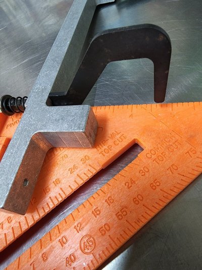
As for the brackets, it seems like it would be pretty easy to make your own if someone had one for reference. They are just metal bars with two spring loaded hooks, and the hooks aren't really even that important from what I can figure. The hooks just wrap around the ball joints and hold the tool up against the knuckle, but it's the dimensions of the metal bar that are what key off the knuckle to give the kingpin inclination angle. Would be nice if someone had a set they could measure up as I bet you could fab up your own set pretty easily. The gen 2 ones seem to be all over the place, but the gen 3/4 ones still go for some silly high prices for what they are.
As for the brackets, it seems like it would be pretty easy to make your own if someone had one for reference. They are just metal bars with two spring loaded hooks, and the hooks aren't really even that important from what I can figure. The hooks just wrap around the ball joints and hold the tool up against the knuckle, but it's the dimensions of the metal bar that are what key off the knuckle to give the kingpin inclination angle. Would be nice if someone had a set they could measure up as I bet you could fab up your own set pretty easily. The gen 2 ones seem to be all over the place, but the gen 3/4 ones still go for some silly high prices for what they are.
Michael Murray
Enthusiast
Excellently thorough reply, thank you! What degree does the OEM inclinometer read to? .1?
After I read your reply I went on a search again to find a sub-$300 set of adapters and stumbled across this. It says incomplete, but it seems that is only because the right side is not included?
Either way, I plan to make this work and put together a right side.
Any recommendations of a magnetic (or not) inclinometer for use in the meantime?
Please keep me updated on your findings
Thanks!
You must be registered for see images attach
Last edited:
OP
OP
The DRB III reads to 0.1 degrees, though the sensors might be capable of more. I did play around with them some more and took some measurements against a digital inclinometer I have and the output appears to be linear. And I was wrong before, it's actually 6 byte output, which is pretty crazy resolution, though I'm not sure if the sensors can actually really read that reliably or not. The DRB also reads things as -180 to +180, so I need to do some testing on "negative" outputs to confirm how they work. Need to check on the zero function as well. It's easy enough to do in software (just apply an offset), but I don't know if the DRB actually sends a command to the sensors and the zero is stored internally on them or if it's just handled purely on the DRB III.
I thought about it some more, did a little testing, and I'm pretty sure I can actually power the system from a computer USB as well. Though the DRB powers the switch box with 12v, there is a 5v regulator inside it that runs pretty much everything else. The DRB also only outputs 5v on the line it uses to switch between left and right sensors. I realized a 5v regulator doesn't have to have 12v fed to it to work, it just wants 5 or more.
So my plan at the moment is a custom cable that would plug into the switch box on one end and the other end will have a DB9 connector, a switch, and a USB connector. The USB is there strictly for power and pulls 5v from the computer to run things. The switch will let you toggle back and forth between reading the right or left sensor (I'm not sure a good way to automate this just yet so both can be read at once like the DRB III does). This way you wouldn't have to fiddle around with a separate power supply or two cables or anything like that. Messed with it a bunch yesterday and was having a hard time understanding the cable, but I think it finally hit me what I was doing wrong, so planning to take another stab at it today. If the cable and power part is solved I just have to figure out the software side, which is going to be a little more interesting. The actual functional side of the program is pretty dirt simple, it's just a matter of figuring out what to code it in and how to talk to a serial port. I have very little experience with talking to hardware on Windows based computers, but I'm hoping I can make something work.
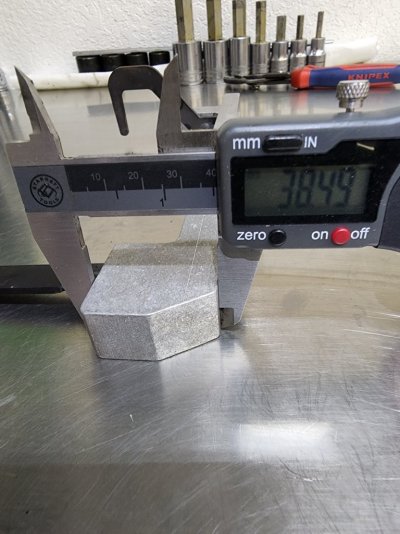
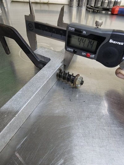
On a different note, any chance you could measure that tool up once you get it? I'm pretty sure the only difference between left and right are the hooks, so would think if you have one you could make another pretty easily by just mirroring things. If you can measure the main block part I think it would be really easy to recreate and I'd be interested in trying to make one myself. As for sensors, I'm pretty sure that tool is aluminum, so don't think a magnetic one is going to do you much good. Most of the ones I see are longer and meant to be more like a level, which isn't really that useful here. The factory ones are pretty compact and nicely machined to be square. There might be something out there though, I just haven't looked that much. The ones I have came in an alignment kit I got as a Christmas present a few years ago. They are more like the level style though and pretty long.
I thought about it some more, did a little testing, and I'm pretty sure I can actually power the system from a computer USB as well. Though the DRB powers the switch box with 12v, there is a 5v regulator inside it that runs pretty much everything else. The DRB also only outputs 5v on the line it uses to switch between left and right sensors. I realized a 5v regulator doesn't have to have 12v fed to it to work, it just wants 5 or more.
So my plan at the moment is a custom cable that would plug into the switch box on one end and the other end will have a DB9 connector, a switch, and a USB connector. The USB is there strictly for power and pulls 5v from the computer to run things. The switch will let you toggle back and forth between reading the right or left sensor (I'm not sure a good way to automate this just yet so both can be read at once like the DRB III does). This way you wouldn't have to fiddle around with a separate power supply or two cables or anything like that. Messed with it a bunch yesterday and was having a hard time understanding the cable, but I think it finally hit me what I was doing wrong, so planning to take another stab at it today. If the cable and power part is solved I just have to figure out the software side, which is going to be a little more interesting. The actual functional side of the program is pretty dirt simple, it's just a matter of figuring out what to code it in and how to talk to a serial port. I have very little experience with talking to hardware on Windows based computers, but I'm hoping I can make something work.
On a different note, any chance you could measure that tool up once you get it? I'm pretty sure the only difference between left and right are the hooks, so would think if you have one you could make another pretty easily by just mirroring things. If you can measure the main block part I think it would be really easy to recreate and I'd be interested in trying to make one myself. As for sensors, I'm pretty sure that tool is aluminum, so don't think a magnetic one is going to do you much good. Most of the ones I see are longer and meant to be more like a level, which isn't really that useful here. The factory ones are pretty compact and nicely machined to be square. There might be something out there though, I just haven't looked that much. The ones I have came in an alignment kit I got as a Christmas present a few years ago. They are more like the level style though and pretty long.
OP
OP
Well, looks like my USB powered hopes are dead. Per the datasheet the regulator cuts out at 7V. In testing I got it all the way down to 5.5-6V, but the USB port runs at a pretty regulated 5, so the regulator doesn't turn on to get everything else going when attempting to power directly from USB. I could potentially power it from one of the extra pins on the serial adapter I have, but those seem to run anywhere from 6-12V. The bigger issue that comes from that is that my switch idea to swap between reading the left and right sensors kind of goes up in smoke there as it requires a 5V signal to operate. I could make it work with an inline regulator, but that just adds more complexity into the cable than I think makes sense. Reading a single sensor should be pretty easy though as I can just jumper the "sensor select" line to ground to only read from the one all the time. At that point the serial port power approach probably also makes sense as it would mean I could do everything in a single connector.
Michael Murray
Enthusiast
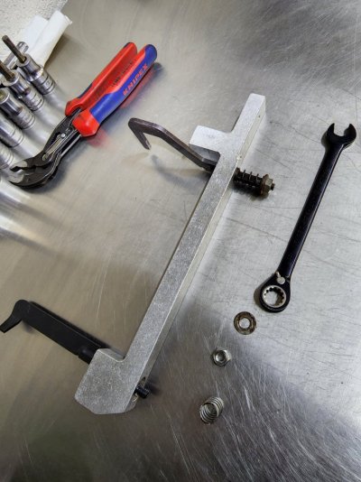
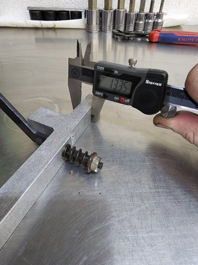
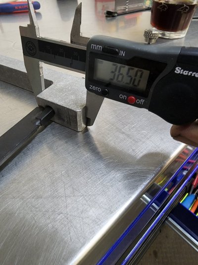
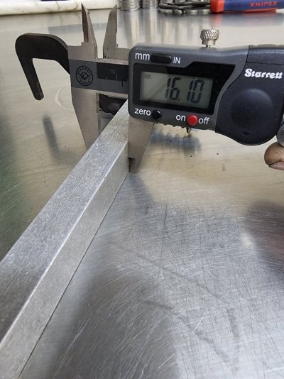
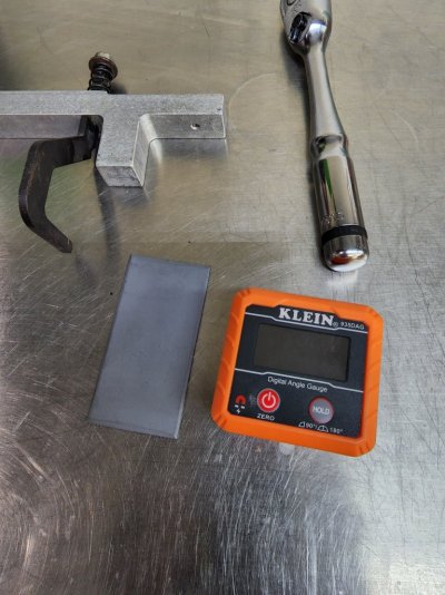
Wow you have really dug into that project, nice work! I found all it takes to get the left side to work on the right is remove the nuts and flip the hooks.
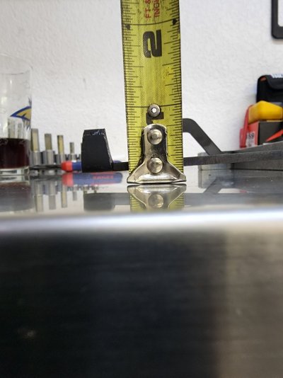
I plan on ******** a piece of steel plate (shown primered) to the bracket and sticking the magnetic digital angle finder to it.
I plan on ******** a piece of steel plate (shown primered) to the bracket and sticking the magnetic digital angle finder to it.
Attachments
Last edited:
Michael Murray
Enthusiast
Michael Murray
Enthusiast
Michael Murray
Enthusiast
OP
OP
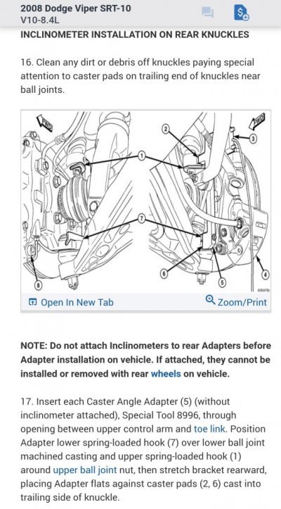
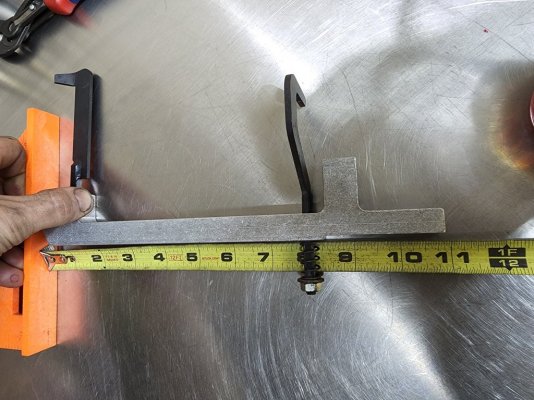
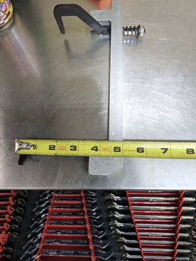
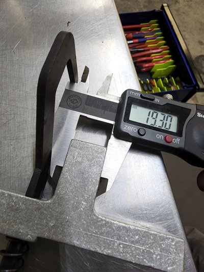
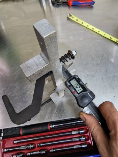
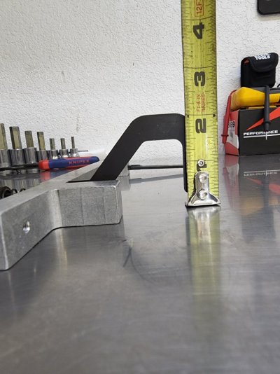
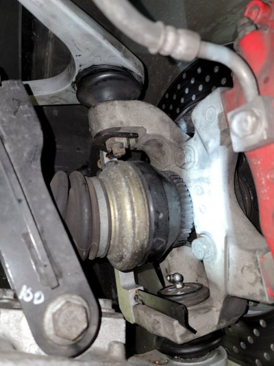
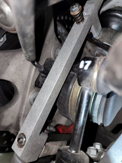
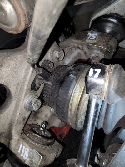
Ah, very nice to see it actually installed on a car with better angles. That makes more sense about how it all fits and goes together. I had a feeling there were some pads on the knuckle casting this tool sat against, and those pictures make that very clear. I might have to CAD up the tool in my spare time just for the heck of it so I've got something for reference. Should be easy enough since it's a pretty simple shape. Looks like there are basically just two tooling points to worry about as well, the rest is just clearance for the parts around it. I'm kind of tempted to even try 3D printing one out of plastic just for some test fitting. If I can get it rigid enough it should probably still work even, though I might have to get clever with how I attach it to the knuckle.
Thanks again for the measurements! I've got more info on the sensor reverse engineering in the "DRB III Reverse Engineering" thread on this same forum. I'm tantalizingly close to something that should work fairly effectively, just have to get the last bugs worked out.
Thanks again for the measurements! I've got more info on the sensor reverse engineering in the "DRB III Reverse Engineering" thread on this same forum. I'm tantalizingly close to something that should work fairly effectively, just have to get the last bugs worked out.
OP
OP
So a couple of things. Firstly, I got a full set of the brackets for my birthday, so I can take some measurements on them myself as well and make up some engineering style drawings if anyone is ever interested in having a set built from scratch. Secondly, and something I found more interesting, one pair of my brackets is actually steel and all the others are aluminum. Don't know if it's just what they had around at the time or if it was an intentional change for more durability or something, but it would mean not needing a plate to use a magnetic inclinometer. They are the rear ones in my case. The gen 2 set I have is all aluminum and the front gen 3 ones I got are aluminum as well.
Lastly, I finally got my inclinometer program working today, so I've got a setup that lets me read the factory inclinometers with a regular computer instead of a DRB III. I still have a little work I'm planning to do on it as I need to add the zero function and do some more testing to verify accuracy, but at least I'm getting actual data out of it now. Would require a "special" cable and external power supply of some variety (could use a cigarette lighter or a wall plug in, just needs to be 12V). The cable is fairly easy to make though, more or less just a straight through serial cable with some wires broken out of it to attach the power supply to.
Lastly, I finally got my inclinometer program working today, so I've got a setup that lets me read the factory inclinometers with a regular computer instead of a DRB III. I still have a little work I'm planning to do on it as I need to add the zero function and do some more testing to verify accuracy, but at least I'm getting actual data out of it now. Would require a "special" cable and external power supply of some variety (could use a cigarette lighter or a wall plug in, just needs to be 12V). The cable is fairly easy to make though, more or less just a straight through serial cable with some wires broken out of it to attach the power supply to.
Michael Murray
Enthusiast
Daaang full set eh? Living the high life I see! To get my angle finder to stick to the bracket I drilled two holes and cut the drill bit I used and epoxied the pieces in there. Works quite well.
OP
OP
Lol, yeah, it wasn't really my intention to have the alignment fixtures for both gens, but that's just kind of how things worked out. Was easier to buy the 6990 kit to get all the other suspension tools that are common between gens. I don't recall ever seeing a similar kit that was specific to the gen 3/4. I think the brackets were the only new parts, so guessing they would have just been an add on kit. I would consider selling them, but my mom has a 94 and I've been meaning to see if they will work on hers. I know the gen 1 was a little more unique and has tubular control arms, but guessing the knuckle is still cast and might be common to a gen 2.
I have got quite the collection of dealer tools going though. I have a big cabinet in my garage and one shelf is pretty much all Viper stuff I've been collecting over time. I rebuilt my engine a few years back due to a spun rod bearing and that was were a lot of it started. Got several of the engine specific tools like the lift fixtures, cam gear puller/installer, and damper puller/installer. The 6990 kit has the majority of the suspension service pieces and can be found fairly cheap from time to time. I don't remember what I paid for mine, but I want to say it wasn't any more than $300 and might have even been under $200. The best tool I've probably ever bought though and the one that has gotten the most use is the ball joint popper. That thing is just wonderful and can actually be used in a lot of places. I've replaced pretty much all the boots on my ball joints now and that tool makes it so easy and safer on parts. Definitely work picking up.
I went through my service manual and made a pretty full list of all the tools that I thought I'd ever want or use. Some of them are really fairly generic and stuff you can buy at a parts store easily enough. Others are so specialized I don't think I'd ever really use them anyway. Others still are ones you could probably make yourself or improvise to some degree. The height gauges are one example I've been looking at. They seem to go for pretty high prices for what they are. It's really just a flat tube that goes between the inside of each wheel to give you a reference point to measure up to frame for ride height. I've been debating how I might make a set and honestly a 2x4 cut to the right size would do the same exact job if it's nice and flat. The official tool is just adjustable to work on more cars.
Dan-o
Enthusiast
Great info, thanks! So did either of you guys figure out if the 6925/6916 adapters work on the ZB Chassis? Or do you have to use the 899x adapters? Are they drilled for the inclinometers? I don’t see inclinometer mounting holes in the ones is see on fleabay. Any chance I can get a copy of that spreadsheet? I’m starting to collect tools now, some viper specific tools I’ll need, others I have acceptable substitutes.
OP
OP
You have to use the 899X ones for the gen 3+, they are reasonably different. Holes should be on both though. The one thing I did find a bit odd is that the front adapters I have seem to be aluminum while the rear adapters are steel or stainless or something. They are significantly heavier, though I don't suppose that really makes any real difference. I actually made some CAD style drawings of the earlier adapters I had for someone on here. I think they would be fairly easy to make if you had access to a shop. They aren't really anything that specials, just some chunks of metal with holes and flats in specific places. Could potentially even weld something together with square tubing if you were accurate enough and did a little post processing to make sure the datums were correct.
As for the tool list, this is what I came up with out of my 04 service manual:
I don't know that it's a 100% exhaustive list, and many of those could probably be replaced with general versions. I'm guessing Dodge often picked a "standard" tool their dealers might already have, like the hose clamp pliers or a lot of the electrical connector depinning tools. The engine and suspension stuff are the ones I focused on as those are the ones that I think would get the most use over time. I think the manual also includes stuff like compression and cooling system pressure testers that I didn't bother to include.
As for the tool list, this is what I came up with out of my 04 service manual:
| Tool | Use |
| 6573 | Rear Axle Bearing/Seal Installer |
| 6761 | Ball Joint Installer |
| 6914 | Height Gauges |
| 6969B | Bushing Remover/Instaler |
| 6983 | Ball Joint Spacer |
| 9096 | Suspension Stands |
| C-4150A | Ball Joint Remover |
| C-4171 | Driver Handle |
| MB991113 | Tie Rod End Remover |
| 9024 | Shock Absorber Wrench |
| CT-1003 | Puller |
| 8995 | Front Caster Adapter |
| 8996 | Rear Caster Adapter |
| 8997 | Height Gauge Extension |
| 7663 | Inclinometer |
| 9052 | Half Shaft Puller |
| 6573 | Bearing/Seal Installer |
| 6958 | Yoke wrench |
| 7794-A | Seal remover |
| C-452 | Yoke Puller |
| C-3718 | Installer |
| 8889 | Seal Installer |
| 6366 | Brake piston retractor |
| 6454 | Brake piston cover |
| 6921 | Master cylinder pressure bleed cap |
| C-3339A | Dial indicator |
| 6638 | Clutch line disconnect |
| 8495 | Hose clamp pliers |
| 6807 | Electrical probe kit |
| 6680 | Terminal pick kit |
| 6932 | Terminal removal tool |
| 8638 | Terminal removal tool |
| 6934 | Terminal removal tool |
| 9057 | Engine lift brackets |
| 8194 | Crankshaft insert |
| 9055 | Crankshaft damper installer |
| 9056 | Crankshaft damper remover |
| 5048 | Puller |
| 8990 | Bearing/Seal remover |
| 9058 | Pilot bearing installer |
| C-4679A | Crankshaft seal remover |
| MD-998306 | Crankshaft seal installer |
| 9060 | Rear crankshaft seal installation guide |
| MD998772A | Valve spring compressor |
| 9005 | Disconnect tool |
| OT-CH6010A | DRB III |
| 6856 | Fuel module spanner wrench |
| C4907 | O2 sensor socket |
| 6893 | Power steering line adapters |
| 8875 | Disconnect tool |
| 9081 | Power steering line adapters |
| C-4755 | Trim removal stick |
| 6990 | Tool set, includes 6969 bushing installer/remover and 8995/8996 caster brackets |
I don't know that it's a 100% exhaustive list, and many of those could probably be replaced with general versions. I'm guessing Dodge often picked a "standard" tool their dealers might already have, like the hose clamp pliers or a lot of the electrical connector depinning tools. The engine and suspension stuff are the ones I focused on as those are the ones that I think would get the most use over time. I think the manual also includes stuff like compression and cooling system pressure testers that I didn't bother to include.
GTS Dean
Enthusiast
An 18mm crowfoot line wrench is just about mandatory for the hydraulic lines at the steering rack.
Dan-o
Enthusiast
Awesome thanks a bunch!!
")
GTS Dean
Enthusiast
I have a DRB and Gen 1-3 Service Tools, plus ball joint and tie rod end separators.
Similar threads
- Replies
- 2
- Views
- 349
- Replies
- 10
- Views
- 12K
- Replies
- 5
- Views
- 358