There have been multiple threads that have discussed the replacement of the OEM Viper in-the-bottle fuel pump with either an external or a double and triple pump in the tank with custom hangers. I took another route and installed a Gen 3 pump into a 1997 Gen 2 . The pump was installed into the 1997 OEM bottle. I took some notes and pictures during the install, the following are some observations. Let me preface this by saying I am by no means a fuel pump expert, what follows are my observations and some easily substantiated calculations.
Some may be surprised, however, if you add a Boost-A-Pump (BAP) to a 255 liter/hr pump you can maintain approximately 850 hp.
If anyone wants to add to or correct this post please feel free. This write-up assumes the Gen 2 has a 190 LPH pump and the Gen 3 has a 255 LPH pump.
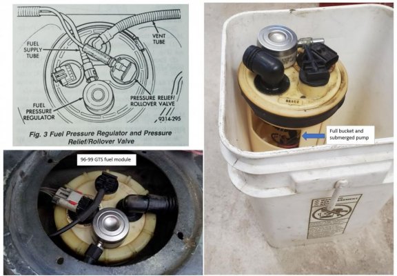
1. THE OEM FUEL SYSTEM
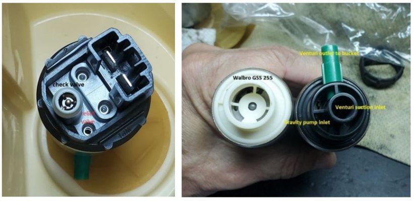
The viper OEM fuel set-up is a two stage pump in a bottle that sits inside the tank. The bottle acts as a reservoir and keeps the fuel supplied to the engine during acceleration when fuel is low in the tank. Several high power cars have the same set-up, Mustangs and Camaro’s are some examples..
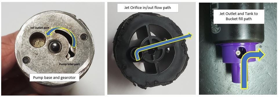
The pick-up tube that extends out of the pump and fits into the bottom of the bottle pulls fuel from the bottom of the tank and fills the bottle, There is a pick-up orifice closer to the pump body that supplies the engine. There is a donut/washer on the inside bottom of the bottle that the pump sits on, that washer keeps the fuel trapped in the bottle. Under normal operating conditions the bottle is always full, therefore, acting as a reservoir that keeps the fuel flowing during hard straight-ahead acceleration or hard cornering, especially when the tank is less than ½ full.
The tank is approximately 10"H x 29"W x 18"D. It is almost a true rectangle, with a dog bone shape to the rear and a bubble on the front. The bottle sits close to the center of the tank. The bottle pick-up sits directly on the bottom of the tank. When my gauge says ½ full, the fuel is 4" above the bottom. From the dimensions and the bottle location it is easy to see how the fuel pick-up can go dry during acceleration or cornering if the bottle did not act as a reservoir.
2. THE Gen 2 VIPER FUEL PUMP HAS LIMITATIONS
If you look at the following table, the 190 LPH pump is not capable of much more than 500 NA rwhp, a key exception would be a nitrous car. Higher hp NA applications might also work, but, at reduced fuel pressure, therefore, requiring some tricky a/f tuning. If you remove my 10% safety margin from the table the 190 LPH pump might give you 525 rwhp for a NA car. If a little tuning you might go a bit higher. A nitrous car could probably exceed 600 hp. The point is the hp is limited by the 190 LPH fuel pump. All these are border line and you are walking the edge. When I ran a single stage nitrous at 625 hp I could not hit my target a/f of 11.5, the car just ran out of fuel pump.
Please keep in mind this table is theoretical, however, the basis is manufacturer’s data, the variable is the car fuel system set-up. Use the table as a starting point, but, consult your tuner for a final solution. The input data for this table came from the Kenne Bell website and the Auto Performance Engineering website
3. AN AFTERMARKET FUEL PUMP AND A NEW PROBLEM
The generally accepted fix is a to install an external fuel pump or a double/triple pump set-up inside the tank. This post is not about the technical aspects of a double or triple pump install, obviously there are a lot of successful installations. However, the problem with any installation that does not use the reservoir bottle with the OEM two stage pump is that at some point (unless the tank is full) you will experience fuel starvation. It could happen in a corner or at the drag strip at the top of first gear. In many cases it will be almost indiscernible, but, if you are logging you will see a drop in fuel pressure and a dip in acceleration.
Even if you use the factory bottle to house a two pump set-up, you will have the same starvation issue unless you are using a two stage OEM pump. If you say you haven’t encountered fuel starvation, you just haven’t driven the car hard enough or have not had the car on slicks, that applies to both drag and track tires. I went to a 255 LPH aftermarket Mustang pump and I would always experience fuel starvation at the drag strip at the top of first gear.. The only way I had to cure my problem was to keep the tank near full, that is an extra 90 lbs or an added 1/10 of sec to the ET.
4. A GEN 3 PUMP WITH BAP:
The Gen 3 pump appears to be a 255 LPH pump. With the addition of a Boost-A-Pump (BAP) to the Gen 3 pump you can possibly take a car approximately 850 hp. This is a very nice option for a medium high hp Gen 2 car.
I can personally substantiate that the 255 LPH pump with a Boost-A-Pump (BAP) will take a nitrous car to 850 rwhp/1000 ft lbs. The BAP is an voltage regulator that has an adjustable set point. The BAP only increases the voltage when you are at or near WOT, the sensitivity is adjustable. The fuel pump is a simple DC motor and as you increase the voltage the pump spins faster giving you more flow.
The previous flow table shows the output of both the 190 LPH and the 255 LPH pumps at 12V, 13,5V, 17.5V and 20V. The MSD BAP actually has a peak output of 22 volts .The input data for this table came from Kenne Bell.
5. INSTALLING THE GEN 3 PUMP INTO A GEN 2
A. THE PARTS
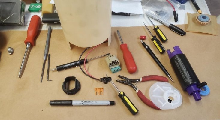
The install is fairly straight forward. You will need the following:
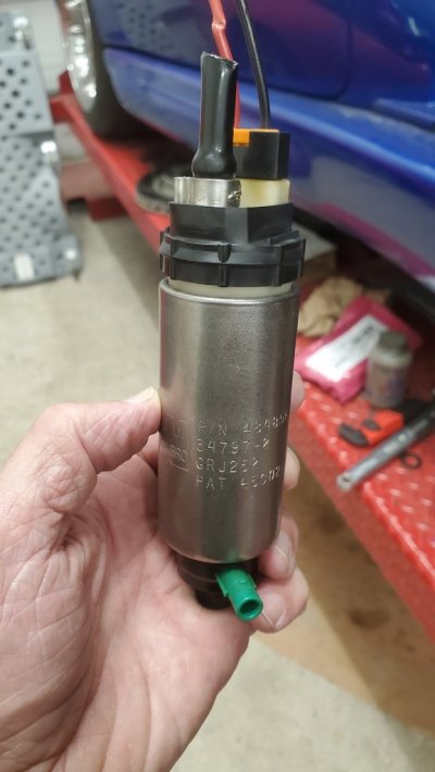
i. Gen 3 pump.
ii. A Gen 3 in-the-bottle connector harness. This is the two wire connector and associated wires.
iii. A 6" piece of submersible 1/4" gas hose. NAPA part #H315. You can use the old hose, however, I found mine was deteriorating.
iv. Two hose clamps, the more compact the clamps the easier the install.
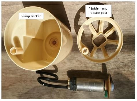
v. The plastic Gen 3 OEM cage (not the hold-down clamp) that goes over the Gen 3 pump. This is pressed on to the pump and in turn the hold down spider in the bottle presses down on this to keep the pump in place
.
vi. The Gen 2 donut/gasket that goes between the bottle and the bottom of the in-the-bottle pump filter. The old donut is probably going to be reusable.
vii. Two female socket terminals. You will use these to terminate the Gen 3 pump connector conductors to the existing Gen 2 in-the-bottle connector. Viper Specialties stocks these terminals. Personally, I would get at least four, just in case a crimp goes wrong.
viii. You will need a crimp tool that does the double fold termination. This is a common automotive crimp.
ix. It is not a bad idea to get connector release tool, it is a small thin screw driver looking tool.
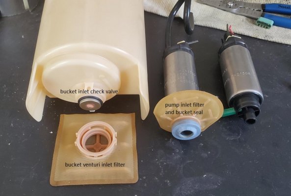
B. THE BOTTLE ASSEMBLY
For information purposes there are two filters on the Gen 2. There is a filter in the bottle and also one on the outside of the bottle, directly on the bottom of the bottle. That filter actually rests on the bottom of the tank. I have a feeling there is more than one fuel filter set-up for the Gen 2, however, that should not impact this install.
This is mostly common sense and it is fair ly simple, here some hints:
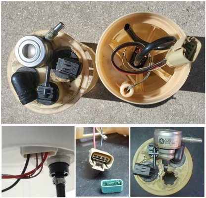
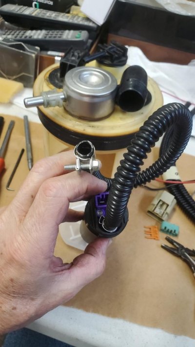
I. The Gen 5 connector that goes into the pump has two wires that must terminate into the four position Gen 2 connector at the top of the bottle, you must remove the original Gen 2 wires and terminate the Gen 5 wires into the top connector. This is where the female terminals are needed.
The connector cap must be removed. This is pushed outward from the back side of the connector. This exposes the release tabs on the inside front of the connector. When you snap the female terminals back in, make sure the short side of the connector goes into the locking tab - when you see them it becomes obvious what is short/long. If you get this wrong the pump will not work or it will work intermittently.
ii. Next, snap on the plastic cage that goes over the top of the Gen 3 pump. This an OEM Gen 3 part and is NOT the Gen 2 hold-down mechanism,
iii. Take the Gen 2 hold-down cage and remove an 1/8" all the way around the inside diameter with a dremel tool. The Gen 2 hold down clamp/spider will not fit over the Gen 3 pump unless you provide this clearance.
iv. You have to cut an 1/8" plus from the Gen 3 pump’s bottom pick-up tube, otherwise it bottoms in the bottle and the donut will not seal.
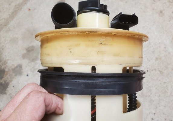
v. Assemble the pump set-up, that means the donut, filter, hose, connector and pump, then place it into the bottle. Put the hold down clamp/spider over the assembly and push down as far as it will go, You will find that it stands approximately 3/8" higher then the Gen 2 did. This means the internal hold-down clamp is not fully seated. Just to make sure it was held in place I put two thin flat head stainless self tapping screws into the bottle/clamp.
C, INSTALLING THE BOTTLE INTO THE CAR.
Again, this is common sense, but, here are some tricks:
i. Slide the bottle/tank gasket over the bottle and position it one inch from the top of the bottle. Coat it with a non-silicon coating like tire sheen, this makes it easier to work into the tank.
ii, Once you have the bottle seated tight against the tank neck you must start the threaded tank hold-down cap, The trick is to mark the starter threads (top/bottom) and position it correctly or it will get cross threaded. Once you have the cap started about ½ turn you can use a 12" 1 X 2 piece of wood with a rubber mallet to gently tap the cap another ½ turn.
If you do not start the cap in the right position, you will not be able to start the threading process.
iii. Lastly, if the fuel line has been off for a while, you will want to squirt some gas into the line, otherwise, you will have a hard time seating the line into the bottles’s male stub, it will bind if it is dry. If you do not seat it completely you take the chance of having it come off under pressure.
Some may be surprised, however, if you add a Boost-A-Pump (BAP) to a 255 liter/hr pump you can maintain approximately 850 hp.
If anyone wants to add to or correct this post please feel free. This write-up assumes the Gen 2 has a 190 LPH pump and the Gen 3 has a 255 LPH pump.
1. THE OEM FUEL SYSTEM
The viper OEM fuel set-up is a two stage pump in a bottle that sits inside the tank. The bottle acts as a reservoir and keeps the fuel supplied to the engine during acceleration when fuel is low in the tank. Several high power cars have the same set-up, Mustangs and Camaro’s are some examples..
The pick-up tube that extends out of the pump and fits into the bottom of the bottle pulls fuel from the bottom of the tank and fills the bottle, There is a pick-up orifice closer to the pump body that supplies the engine. There is a donut/washer on the inside bottom of the bottle that the pump sits on, that washer keeps the fuel trapped in the bottle. Under normal operating conditions the bottle is always full, therefore, acting as a reservoir that keeps the fuel flowing during hard straight-ahead acceleration or hard cornering, especially when the tank is less than ½ full.
The tank is approximately 10"H x 29"W x 18"D. It is almost a true rectangle, with a dog bone shape to the rear and a bubble on the front. The bottle sits close to the center of the tank. The bottle pick-up sits directly on the bottom of the tank. When my gauge says ½ full, the fuel is 4" above the bottom. From the dimensions and the bottle location it is easy to see how the fuel pick-up can go dry during acceleration or cornering if the bottle did not act as a reservoir.
You must be registered for see images attach
2. THE Gen 2 VIPER FUEL PUMP HAS LIMITATIONS
If you look at the following table, the 190 LPH pump is not capable of much more than 500 NA rwhp, a key exception would be a nitrous car. Higher hp NA applications might also work, but, at reduced fuel pressure, therefore, requiring some tricky a/f tuning. If you remove my 10% safety margin from the table the 190 LPH pump might give you 525 rwhp for a NA car. If a little tuning you might go a bit higher. A nitrous car could probably exceed 600 hp. The point is the hp is limited by the 190 LPH fuel pump. All these are border line and you are walking the edge. When I ran a single stage nitrous at 625 hp I could not hit my target a/f of 11.5, the car just ran out of fuel pump.
Please keep in mind this table is theoretical, however, the basis is manufacturer’s data, the variable is the car fuel system set-up. Use the table as a starting point, but, consult your tuner for a final solution. The input data for this table came from the Kenne Bell website and the Auto Performance Engineering website
| 190L Pump (Gen 2) | L/hr | Gal/hr | lbs/hr | lbs/hr w/Safety Margin -10% | Max NA Flywheel HP (BSFC = .45) | Max NA RWHP | Max Boosted Flywheel HP (BSFC = .60) | Max Boosted RWHP | Max Kenne Bell Boosted Recommendation |
| 12V | 123 | 33 | 205 | 185 | 410 | 349 | 308 | 261 | |
| 13.5V | 161 | 43 | 268 | 242 | 537 | 456 | 403 | 342 | |
| 17.5 | 203 | 54 | 338 | 305 | 677 | 575 | 508 | 431 | |
| 255L Pump *(Gen 3) | L/hr | Gal/hr | lbs/hr | lbs/hr Safety Margin -10% | Max NA Flywheel HP | Max NA RWHP | Max Boosted Flywheel HP | Max Boosted RWHP | |
| 12V | 208 | 55 | 346 | 312 | 692 | 589 | 519 | 441 | |
| 13.5 | 246 | 65 | 410 | 369 | 819 | 696 | 614 | 522 | |
| 17.5V | 351 | 93 | 584 | 526 | 1168 | 993 | 876 | 745 | |
| 20V | 440 | 116 | 732 | 659 | 1465 | 1245 | 1099 | 934 | 750-850 |
| 1. Based on 50 psi. | |||||||||
| 2. BSFC can vary dramatically on supercharged applications. | |||||||||
| 3. In high hp applications fuel line losses can reduce max attainable hp. | |||||||||
| * Assumed |
3. AN AFTERMARKET FUEL PUMP AND A NEW PROBLEM
The generally accepted fix is a to install an external fuel pump or a double/triple pump set-up inside the tank. This post is not about the technical aspects of a double or triple pump install, obviously there are a lot of successful installations. However, the problem with any installation that does not use the reservoir bottle with the OEM two stage pump is that at some point (unless the tank is full) you will experience fuel starvation. It could happen in a corner or at the drag strip at the top of first gear. In many cases it will be almost indiscernible, but, if you are logging you will see a drop in fuel pressure and a dip in acceleration.
Even if you use the factory bottle to house a two pump set-up, you will have the same starvation issue unless you are using a two stage OEM pump. If you say you haven’t encountered fuel starvation, you just haven’t driven the car hard enough or have not had the car on slicks, that applies to both drag and track tires. I went to a 255 LPH aftermarket Mustang pump and I would always experience fuel starvation at the drag strip at the top of first gear.. The only way I had to cure my problem was to keep the tank near full, that is an extra 90 lbs or an added 1/10 of sec to the ET.
4. A GEN 3 PUMP WITH BAP:
The Gen 3 pump appears to be a 255 LPH pump. With the addition of a Boost-A-Pump (BAP) to the Gen 3 pump you can possibly take a car approximately 850 hp. This is a very nice option for a medium high hp Gen 2 car.
I can personally substantiate that the 255 LPH pump with a Boost-A-Pump (BAP) will take a nitrous car to 850 rwhp/1000 ft lbs. The BAP is an voltage regulator that has an adjustable set point. The BAP only increases the voltage when you are at or near WOT, the sensitivity is adjustable. The fuel pump is a simple DC motor and as you increase the voltage the pump spins faster giving you more flow.
The previous flow table shows the output of both the 190 LPH and the 255 LPH pumps at 12V, 13,5V, 17.5V and 20V. The MSD BAP actually has a peak output of 22 volts .The input data for this table came from Kenne Bell.
5. INSTALLING THE GEN 3 PUMP INTO A GEN 2
A. THE PARTS
The install is fairly straight forward. You will need the following:
i. Gen 3 pump.
ii. A Gen 3 in-the-bottle connector harness. This is the two wire connector and associated wires.
iii. A 6" piece of submersible 1/4" gas hose. NAPA part #H315. You can use the old hose, however, I found mine was deteriorating.
iv. Two hose clamps, the more compact the clamps the easier the install.
v. The plastic Gen 3 OEM cage (not the hold-down clamp) that goes over the Gen 3 pump. This is pressed on to the pump and in turn the hold down spider in the bottle presses down on this to keep the pump in place
.
vi. The Gen 2 donut/gasket that goes between the bottle and the bottom of the in-the-bottle pump filter. The old donut is probably going to be reusable.
vii. Two female socket terminals. You will use these to terminate the Gen 3 pump connector conductors to the existing Gen 2 in-the-bottle connector. Viper Specialties stocks these terminals. Personally, I would get at least four, just in case a crimp goes wrong.
viii. You will need a crimp tool that does the double fold termination. This is a common automotive crimp.
ix. It is not a bad idea to get connector release tool, it is a small thin screw driver looking tool.
B. THE BOTTLE ASSEMBLY
For information purposes there are two filters on the Gen 2. There is a filter in the bottle and also one on the outside of the bottle, directly on the bottom of the bottle. That filter actually rests on the bottom of the tank. I have a feeling there is more than one fuel filter set-up for the Gen 2, however, that should not impact this install.
This is mostly common sense and it is fair ly simple, here some hints:
I. The Gen 5 connector that goes into the pump has two wires that must terminate into the four position Gen 2 connector at the top of the bottle, you must remove the original Gen 2 wires and terminate the Gen 5 wires into the top connector. This is where the female terminals are needed.
The connector cap must be removed. This is pushed outward from the back side of the connector. This exposes the release tabs on the inside front of the connector. When you snap the female terminals back in, make sure the short side of the connector goes into the locking tab - when you see them it becomes obvious what is short/long. If you get this wrong the pump will not work or it will work intermittently.
ii. Next, snap on the plastic cage that goes over the top of the Gen 3 pump. This an OEM Gen 3 part and is NOT the Gen 2 hold-down mechanism,
iii. Take the Gen 2 hold-down cage and remove an 1/8" all the way around the inside diameter with a dremel tool. The Gen 2 hold down clamp/spider will not fit over the Gen 3 pump unless you provide this clearance.
iv. You have to cut an 1/8" plus from the Gen 3 pump’s bottom pick-up tube, otherwise it bottoms in the bottle and the donut will not seal.
v. Assemble the pump set-up, that means the donut, filter, hose, connector and pump, then place it into the bottle. Put the hold down clamp/spider over the assembly and push down as far as it will go, You will find that it stands approximately 3/8" higher then the Gen 2 did. This means the internal hold-down clamp is not fully seated. Just to make sure it was held in place I put two thin flat head stainless self tapping screws into the bottle/clamp.
You must be registered for see images attach
C, INSTALLING THE BOTTLE INTO THE CAR.
Again, this is common sense, but, here are some tricks:
i. Slide the bottle/tank gasket over the bottle and position it one inch from the top of the bottle. Coat it with a non-silicon coating like tire sheen, this makes it easier to work into the tank.
ii, Once you have the bottle seated tight against the tank neck you must start the threaded tank hold-down cap, The trick is to mark the starter threads (top/bottom) and position it correctly or it will get cross threaded. Once you have the cap started about ½ turn you can use a 12" 1 X 2 piece of wood with a rubber mallet to gently tap the cap another ½ turn.
If you do not start the cap in the right position, you will not be able to start the threading process.
iii. Lastly, if the fuel line has been off for a while, you will want to squirt some gas into the line, otherwise, you will have a hard time seating the line into the bottles’s male stub, it will bind if it is dry. If you do not seat it completely you take the chance of having it come off under pressure.
You must be registered for see images attach
You must be registered for see images attach
Last edited: