Loose harmonic balancer AND crank pulley

doctormosfet

Enthusiast
Joined
Jul 27, 2025
Posts
62
Reaction score
49
Location
Mahopac, NY
Make sure the Balancer has a perfectly flat surface to mount the pully against.
Funny that you mention that. I now see that the balancer is far enough in that the outer portion of the balancer hub protrudes from the front of the balancer. Does this mean the balancer is too deep? Or should I get a pulley shim to make up the difference (~ 1/16")? I haven't found any images so far of other Vipers with ATI balancers installed, so I don't really have anything to go by here.
 

doctormosfet

Enthusiast
Joined
Jul 27, 2025
Posts
62
Reaction score
49
Location
Mahopac, NY
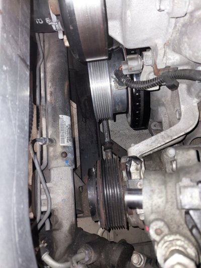
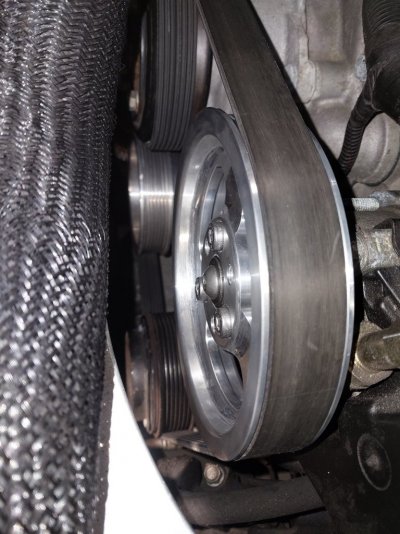
Well, it turns out that fully mounting the balancer onto the hub does, in fact, result in the inner portion of the hub protruding out from the front of the balancer by ~ 1/16". The crank pulley mounts around that portion onto the balancer surface. I was initially hesitant, as the hole in the crank pulley wasn't quite large enough to fit around the inner portion of the balancer hub, and that had me thinking I must have pressed too hard onto the balancer and maybe started to crush it, but no. There were simply some surface imperfections on the inner portion of the crank hub and the inner hole of the crank pulley. So I dremeled out the inner hole of the crank pulley slightly, using a sanding bit, and then followed up with emory paper to smooth it out (I also filed the outer portion of the crank hub, to try to smooth out any damage from prior hammering). Only needed to remove a very small amount and the crank pulley just slots right on there, with correct alignment to the other pulleys.

ATI manual says to use 3/8" longer bolts to mount the pulley. I initially thought that would be 1.125" but that is too long, so I went to 1" bolts and those did the job (blue loctite and 30 lb-ft).
 

Attachments

  • crank pulley done.jpg
    crank pulley done.jpg
    151 KB · Views: 8
  • belt done.jpg
    belt done.jpg
    158.8 KB · Views: 8
  • crank pulley 2.jpg
    crank pulley 2.jpg
    158.9 KB · Views: 8
Last edited:

emjohn43

Enthusiast
Joined
Sep 2, 2024
Posts
27
Reaction score
13
Location
Ohio
Looks great. I have a ATI damper as well as a crank pin kit, sitting on the shelf waiting for winter, as well as an IPSCO crank pulley (OEM diameter) on the way.

Thanks for being the test mule on this one!
 

GTS Dean

Enthusiast
Joined
Jul 22, 2000
Posts
4,153
Reaction score
480
Location
New Braunfels, Texas
The projection is also called a centering register, or pilot. It's purpose is to keep the pulley true with the crank axis. The bolts resist the loading caused by the accessories being driven off the crank. The aluminum IPSCO mounting surface is noticeably thicker than the OE steel piece, but only requires slightly longer bolts. If the IPSCO pulley does not fully seat against the damper because the center hole is undersized vs the register, THAT is a problem that causes pulley groove misalignment.
 

GTS Dean

Enthusiast
Joined
Jul 22, 2000
Posts
4,153
Reaction score
480
Location
New Braunfels, Texas
I measured my IPSCO pulley last night and its pilot hole is 2.5" ID. It's been off for a few months waiting on my engine rebuild.
 

doctormosfet

Enthusiast
Joined
Jul 27, 2025
Posts
62
Reaction score
49
Location
Mahopac, NY
I measured my IPSCO pulley last night and its pilot hole is 2.5" ID. It's been off for a few months waiting on my engine rebuild.
All of my stuff is mounted already, so I haven't had a chance to measure the OD of the centering register on the ATI hub. I'd imagine it should be slightly under 2.5" and my issue was possible caused by some nicks around the edges.
 
Top